
Trailer mule vehicle for moving semi-trailers

Active Publication Date: 2006-04-06
HAMMONDS TECHN SERVICES
View PDF34 Cites 11 Cited by
  • Summary
  • Abstract
  • Description
  • Claims
  • Application Information

AI Technical Summary

Benefits of technology

[0008] A primary object of this invention is to provide a service vehicle which is designed and arranged for moving semi-trailers with enhanced maneuverability.

Problems solved by technology

Space is normally at a premium resulting in limited maneuvering space within the yards.
A large turning radius makes maneuvering around tight areas difficult and often dangerous.
In a congested location, hazards from reversing are increased.
Even with shortened terminal tractors, it is often difficult, even for a skilled operator, to park a semi-trailer against a wall in a slot or stall between two other trailers.
In some instances, a backing maneuver cannot be accomplished without uncoupling the trailer, moving the tractor to a more favorable angle, and re-coupling the trailer to complete the move.
It is also time consuming to back a conventional terminal tractor fifth wheel plate into engagement with the king pin of the trailer even with the V-shaped slot and the double-oscillation mount common with fifth wheel plates.
Precision maneuvering is required while the driver must look backward resulting in operator fatigue and inefficiency.
The hitching operation is further complicated in the instances where a pintle hook / gudgeon hitch is used in place of the fifth wheel plate / king pin hitch.
The '608 vehicle lacks tractive force because of the single drive wheel.
A single drive wheel must be rotated in order to change the vehicle direction, and although the single drive wheel can be turned to direct the vehicle in any direction, it does not provide directional stability for the case where a force is exerted on the vehicle from an angle to the line of intended travel.
For example, a force against the '608 vehicle at a 20 degree angle to the right or left of the line of travel would force the single '608 wheel to skid, causing loss of directional control.

Method used


Image

  • Trailer mule vehicle for moving semi-trailers
  • Trailer mule vehicle for moving semi-trailers
  • Trailer mule vehicle for moving semi-trailers

Examples


Embodiment Construction

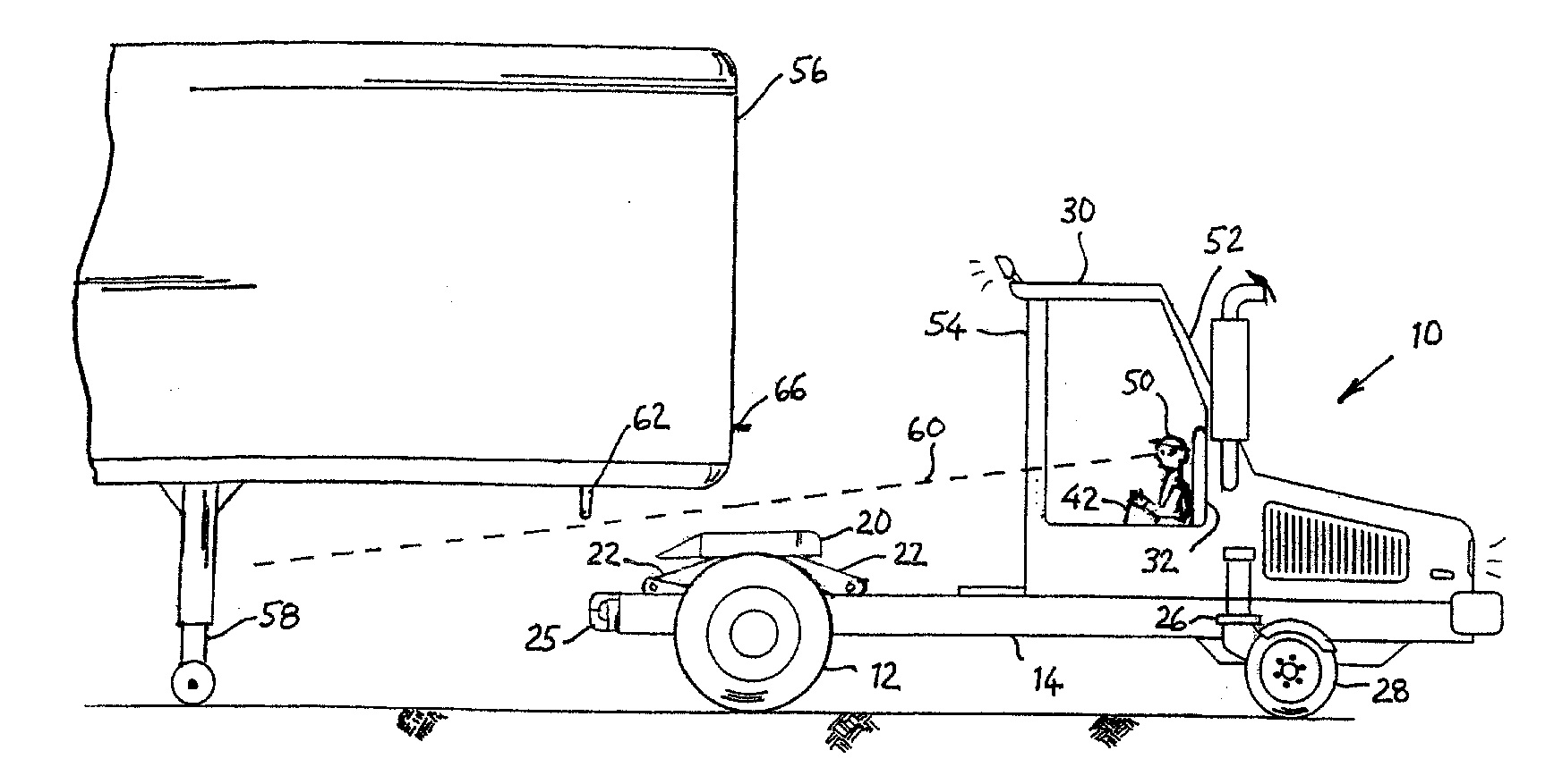
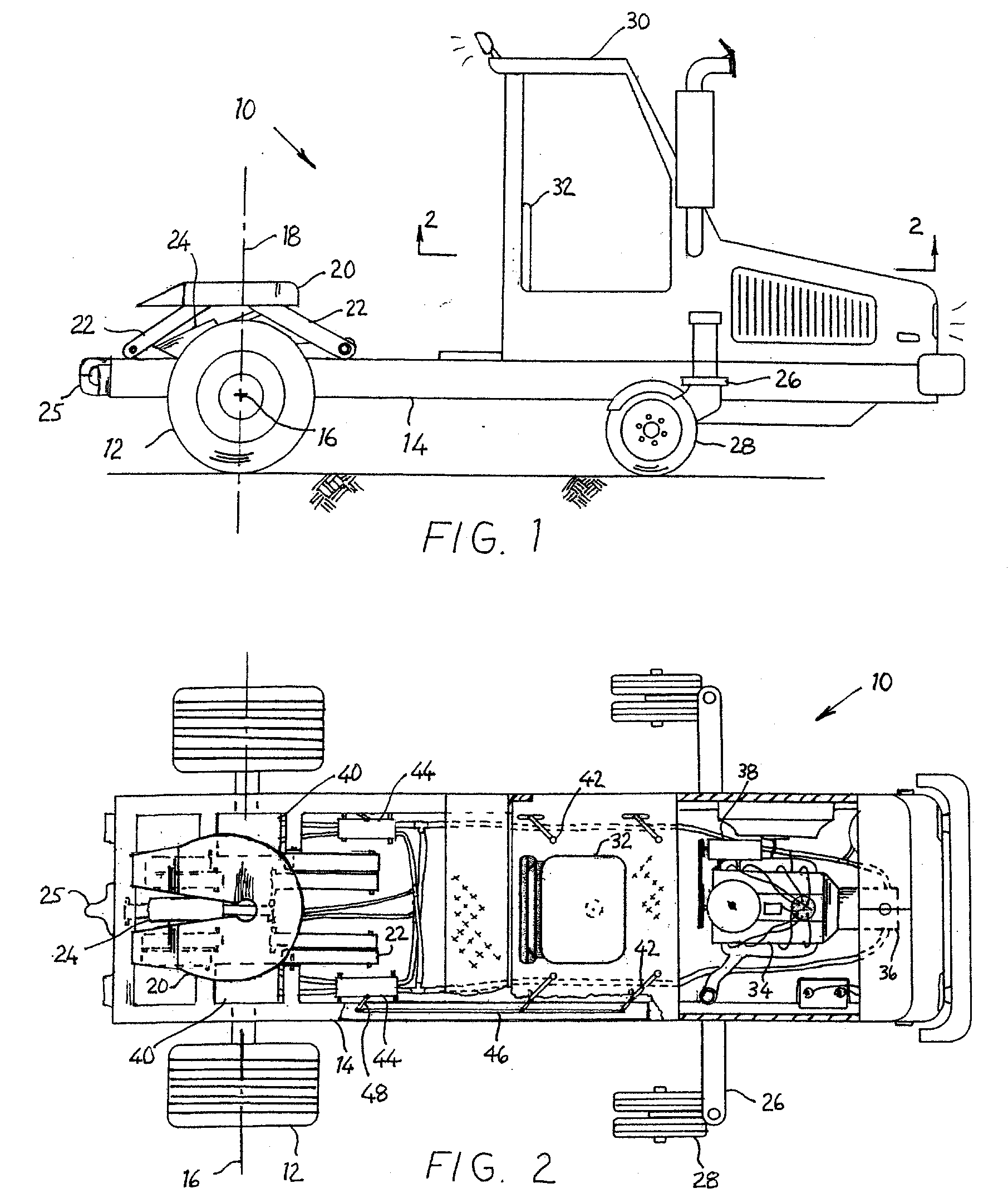
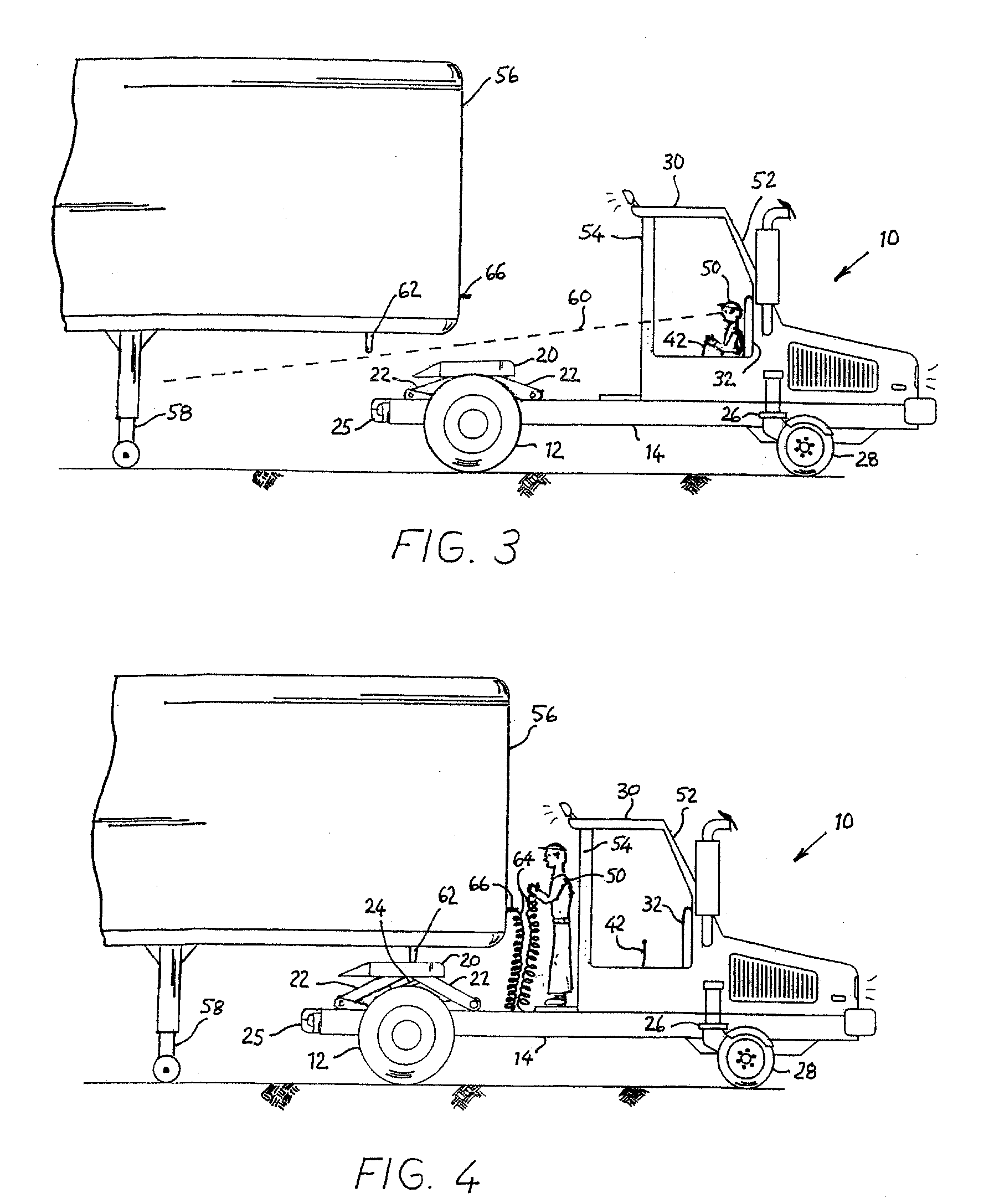
[0027] As shown in FIGS. 1 and 2, the trailer mule vehicle 10 includes primary drive wheels 12 mounted on a frame 14. The drive wheels 12 may have single or dual tire configuration. The wheels 12 are mounted along a common horizontal axis 16. A vertical axis 18 is centered between the drive wheels 12 and intersects the horizontal axis 16. Attached to frame 14 forward of drive wheels 12 are two outriggers 26 with distal ends supported by small wheels arranged as swivel casters 28. The caster wheels 28 freewheel and swivel in response to vehicle movement caused by drive wheels 12. The outriggers 26 and swivel caster wheels 28 support the vehicle 10 while allowing it to maneuver in tight spaces. A cab 30 with a driver's seat 32 provides a suitable operating environment for vehicle 10.

[0028] A fifth wheel plate hitch 20 is coupled to frame 14 generally at vertical axis 18 by articulated arms 22. The arms 22 are pivotably connected to the frame 14 and are cross-braced for unitary moveme...


PUM


Abstract

A trailer mule vehicle with a frame, two independent drive wheels located at the rear of the frame on a common axis, two caster support wheels located at the front of the frame, and a fifth wheel plate generally centered between and positioned above the rear drive wheels. Each drive wheel is powered independently of the other and can rotate at variable speeds in either direction. The vehicle is capable of rotation about the center of the fifth wheel plate. The fifth wheel plate is mounted on an articulated arm which raises and lowers the fifth wheel plate for rapid coupling to and transportation of a semi-trailer without the need for retracting the semi-trailer's landing gear.

Description

(1) FIELD OF THE INVENTION [0001] This invention relates generally to a wheeled vehicle designed to turn about a central vertical axis. In particular, the invention relates to powered utility riding vehicles of the type useful for moving trailers about a trailer terminal, truck yard, or warehouse where rotation-in-place steering is advantageous. (2) DESCRIPTION OF PRIOR ART [0002] Within the transportation industry, semi-trailers are often routed through trailer distribution terminals or trailer yards. Space is normally at a premium resulting in limited maneuvering space within the yards. The trailers must often be shuttled about the yards and are typically moved using terminal tractors. Conventional terminal tractors, also known as trailer jockies or yard mules, typically resemble shortened road tractors. They are configured with two axles, one in front, the other in the rear. The rear axle is fixed to the frame of the vehicle and provides motive force via a pair of dual wheels. Th...

Claims


Application Information

Patent Timeline
IPC IPC(8): B62D11/02
CPCB60D1/36
Inventor HAMMONDS, CARL L.
Owner HAMMONDS TECHN SERVICES
Learn More