Height adjustment mechanism and platform

a technology of height adjustment and platform, which is applied in the field of height adjustment mechanism and platform, can solve the problems of laborious and operating inconvenience, limited lifting height, and complex structure of the height adjustment platform, and achieve the effects of simple structure, strong practicality, and convenient manual operation for users

Active Publication Date: 2019-05-14
FOSHAN DESIGNA TECHNOLOGY CO LTD
View PDF76 Cites 2 Cited by
  • Summary
  • Abstract
  • Description
  • Claims
  • Application Information

AI Technical Summary

Benefits of technology

[0009]An objective of the present invention is to provide a height adjustment mechanism having a simple structure, being applied on any one product which is needed to be adjusted the height thereof, and being convenient to use. The present invention further provides a height adjustment platform including the height adjustment mechanism. The height adjustment is convenient to use and decreases the operation space to improve the universality. The present invention further provides a height adjustment method.

Problems solved by technology

However, manual operation may be not convenient for the user to operate the height adjustment platform.
However, the structure of the height adjustment platform may be complex, and the lifting height may be limited by the location of each position hole.
Thus, it costs time and energy to lift or move down the top part, and it is not convenient for the user to lift or move down the top part.
As such, a large operating space is needed to lift the height adjustment platform.
However, the height adjustment method of the existing height adjustment platform is not convenient to operate, and costs time and energy.

Method used


Image

  • Height adjustment mechanism and platform
  • Height adjustment mechanism and platform
  • Height adjustment mechanism and platform

Examples


first embodiment

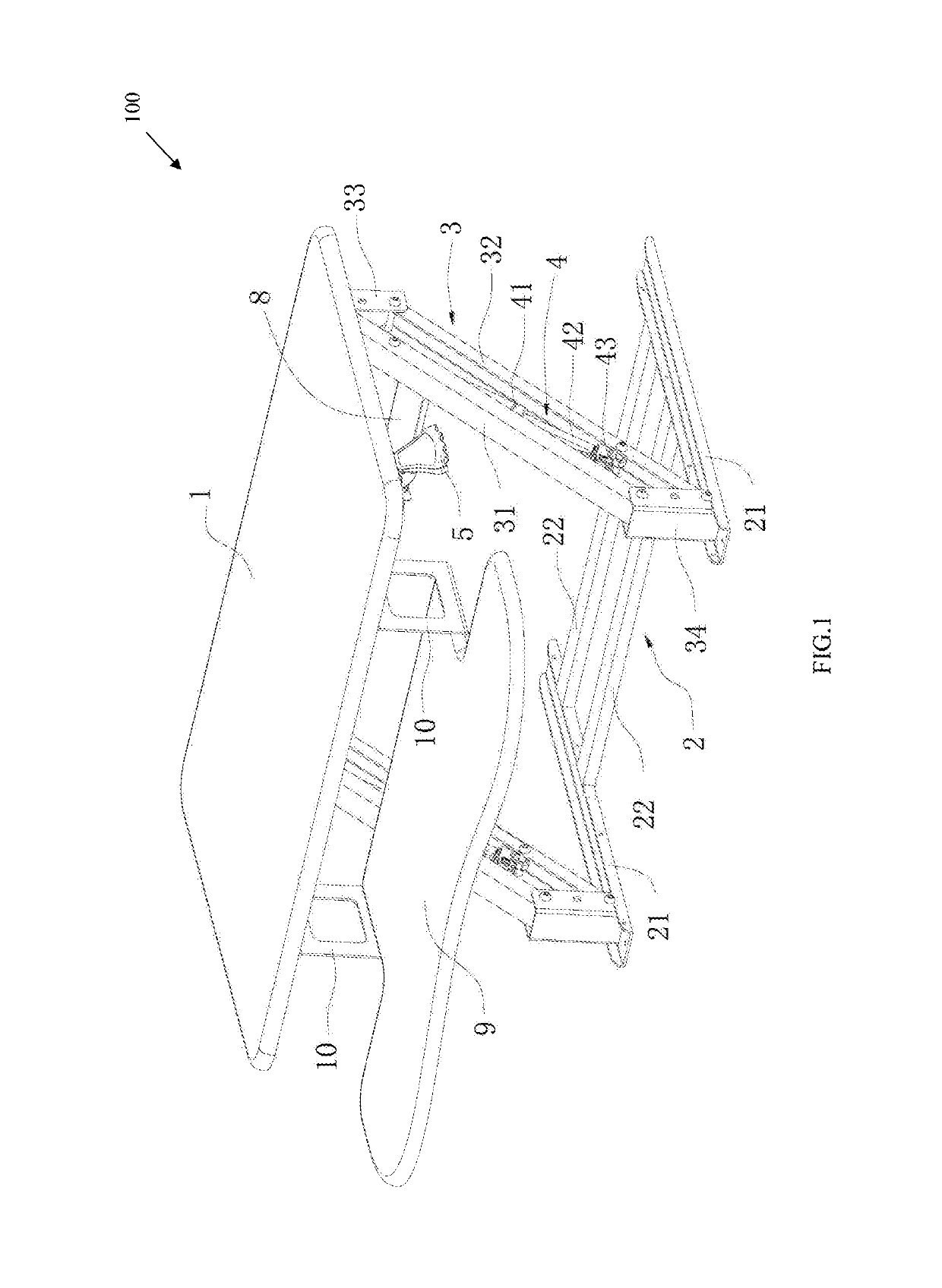
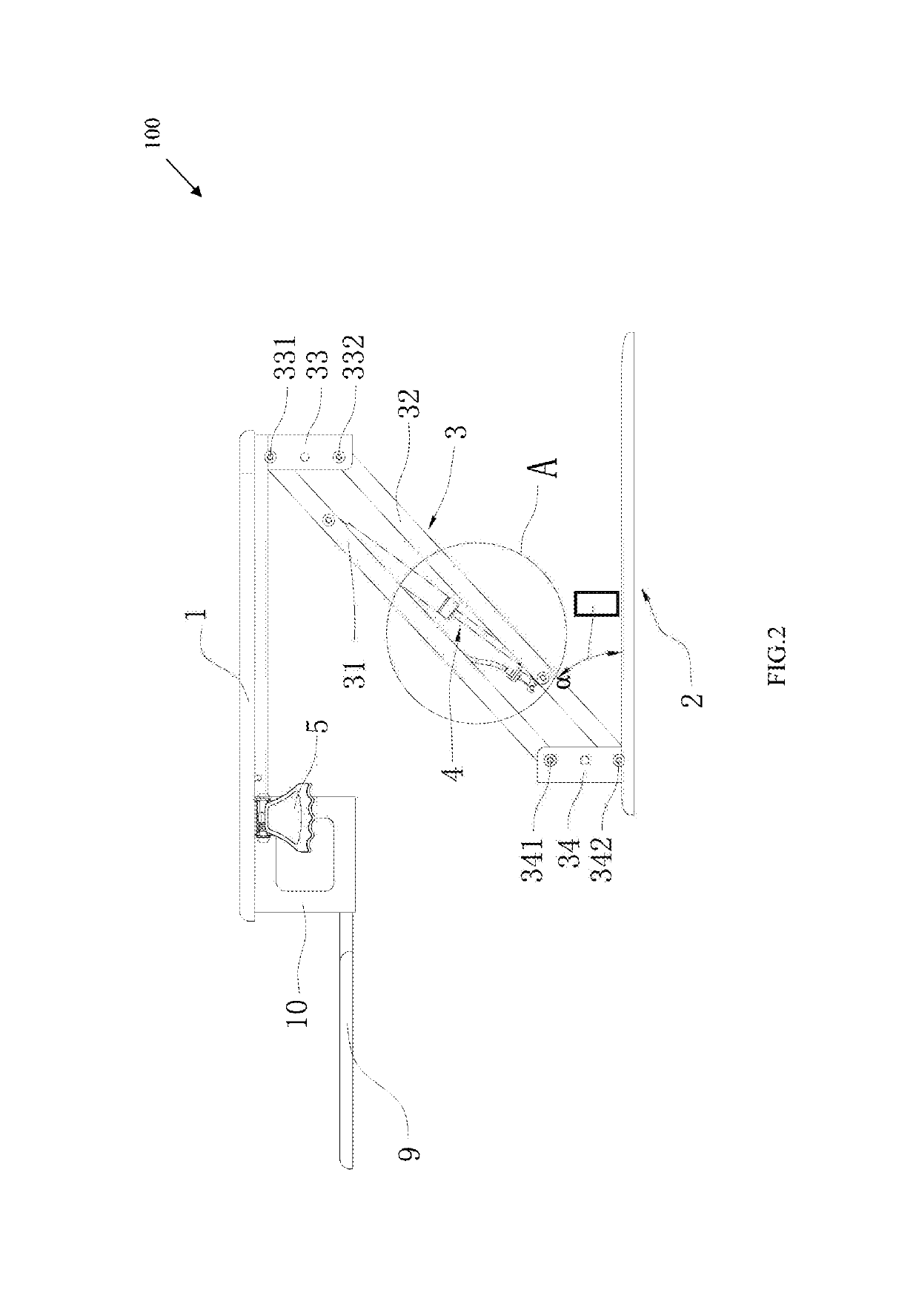
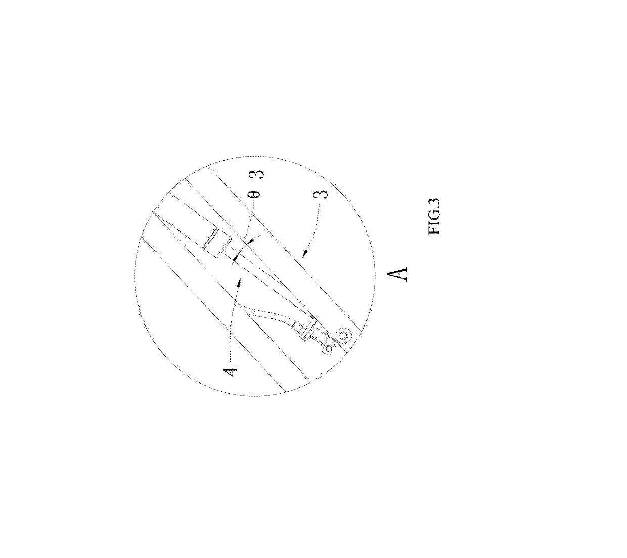
[0061]FIGS. 1-5 illustrate a height adjustment platform 100 of a first embodiment. The height adjustment platform can include a first working table 1, a bottom bracket 2, two lifting arms 3, two driving mechanisms used to drive the lifting arms 3, and a control switch 5 configured to control the driving mechanism. Two ends of each lifting arm 3 can be rotatably coupled to the first working table 1 and the bottom bracket 2, respectively. When in use, the lifting arms 3 and the bottom bracket 2 can rotate an angle α ranging from about 0 to about 60 degrees. The driving mechanism can be mounted on one lifting arm 3, and there can be an angle θ3 formed between the driving mechanism and the corresponding lifting arm 3.

[0062]The lifting arm 3 can include a first rod 31, a second rod 32, a first joint device 33, and a second joint device 34. The first rod 31 can be parallel to the second rod 32. Two ends of the first rod 31 can be respectively coupled to the first joint device 33 and the s...

second embodiment

[0076]FIG. 6 illustrates a height adjustment platform 200 of a second embodiment similar to the height adjustment platform of the first embodiment. The difference can be that the self-locking gas spring 4 used as the driving mechanism can be positioned on the bottom bracket 2, the driving mechanism can include a support rod 11. A first end of the support rod 11 can be coupled to the releasing head 43, and a second end of the support rod 11 can extend into the parallelogram structure to connect the rod of the lifting arm 3. An angle θ6 can be formed between the support rod 11 and the rod of the lifting arm 3.

[0077]When in use, the releasing rod 42 of the self-locking gas spring 4 can extend to jack up the lifting arm 3 and the working table via the support rod 11, or the releasing rod 42 of the self-locking gas spring 4 can shrink to move down the lifting arm 3 and the working table via the support rod 11.

[0078]The driving mechanism can be positioned on the bottom bracket 2 to preven...

third embodiment

[0080]FIG. 7 illustrates a height adjustment platform 300 of a third embodiment similar to the height adjustment platform of the first embodiment. The difference can be that the self-locking gas spring 4 used as the driving mechanism can be positioned outside of the parallelogram structure, for example, the self-locking gas spring 4 can be positioned on the bottom bracket 2. The self-locking gas spring 4 can be coupled to the rod of the lifting arm 3, and an angle θ7 can be formed between the rod of the lifting arm 3 and self-locking gas spring 4.

[0081]Other aspects of this embodiment are like those of the first embodiment.


PUM


Abstract

An adjustable tray system is provided. The adjustable tray system may include a working table and a support member, where the support member may attach the working table with a supporting structure. The adjustable tray system may also include at least one adjustment mechanism. The adjustment mechanism may couple the working table with the support member such that an angle is formed between the support member and the working table. The adjustment mechanism may also allow angular adjustment of the working table such that the working table pivots about a rotation point of the adjustment mechanism. The adjustable tray system may be used in conjunction with a height adjustment platform, such as for an adjustable keyboard tray of a height adjustable desk.

Description

CROSS-REFERENCE TO RELATED APPLICATIONS[0001]This application is a continuation-in-part of U.S. application Ser. No. 15 / 224,845, filed Aug. 1, 2016, and entitled “HEIGHT ADJUSTMENT MECHANISM, PLATFORM AND METHOD” and U.S. Design application Ser. No. 29 / 598,176, filed Mar. 23, 2017, and entitled “HEIGHT ADJUSTMENT PLATFORM,” each of which claim priority to CN Application No. 201610388959.6, filed Jun. 6, 2016, which applications are incorporated by reference herein in their entirety.FIELD OF THE INVENTION[0002]The subject matter herein generally relates to a height adjustment mechanism, platform and method, and particularly to a height adjustment mechanism, platform and method used in office.BACKGROUND[0003]In recent years, with the development and popularization of computer technology, more and more people can work or study by computer. To maintain a good posture to prevent occupational injuries, height adjustment platforms can be sold on the market to meet the need of adjusting the...

Claims


Application Information

Patent Timeline
Patent Type & Authority Patents(United States)
IPC IPC(8): A47B9/00A47B21/02A47B9/16
CPCA47B9/16A47B21/02
Inventor HU, YAJUN
Owner FOSHAN DESIGNA TECHNOLOGY CO LTD
Why Eureka
Try Eureka