Filtering method and filtering device

Active Publication Date: 2006-04-06
NIKUNI
View PDF1 Cites 7 Cited by
  • Summary
  • Abstract
  • Description
  • Claims
  • Application Information

AI Technical Summary

Benefits of technology

[0015] The filtering device of the present invention, further comprising: a liquid level sensor for detecting the liquid level of the filter auxiliary agent liquid provided in the pre-coat tank; and a switching valve for switching the filter treatment liquid circulated in the filter circuit to the pre-coat tank when the liquid level detected by the liquid level sensor is below a lower limit setting value. The liqu

Problems solved by technology

Thus, since the filter auxiliary agent separated by backwashing from the filter element is treated as industrial waste, a large amount of filter

Method used


Image

  • Filtering method and filtering device
  • Filtering method and filtering device
  • Filtering method and filtering device

Examples


Embodiment Construction

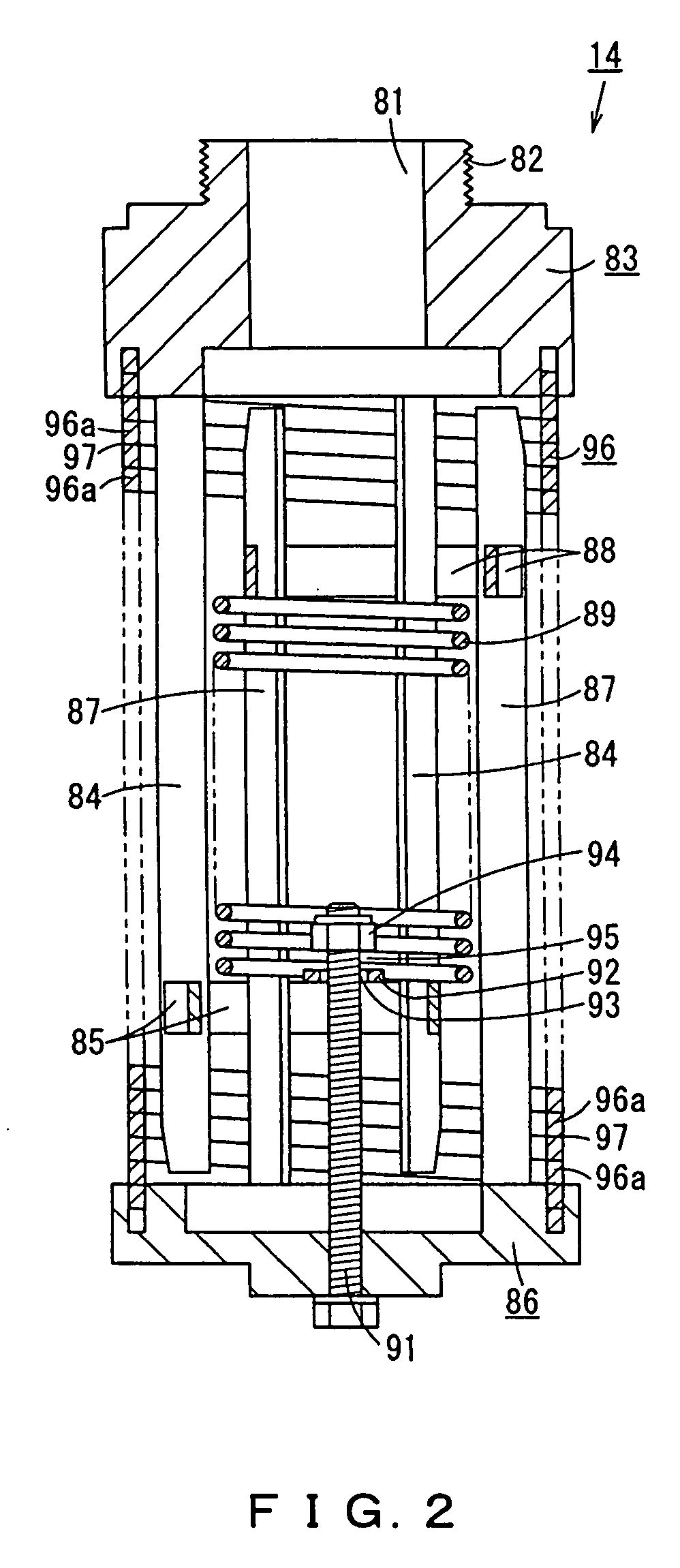
[0018] Hereinafter, the present invention will be described with reference to one embodiment shown in FIG. 1 and FIG. 2.

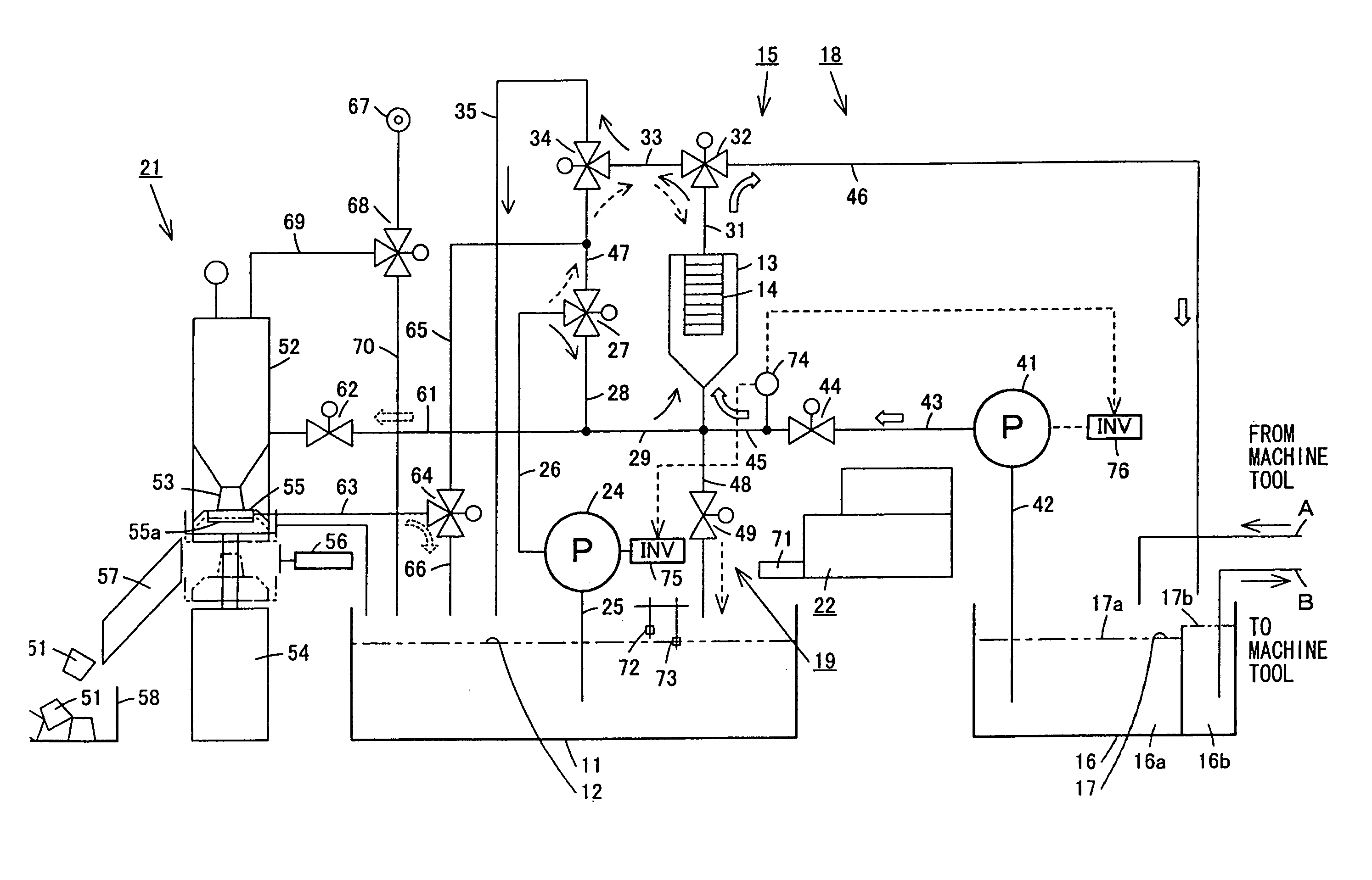
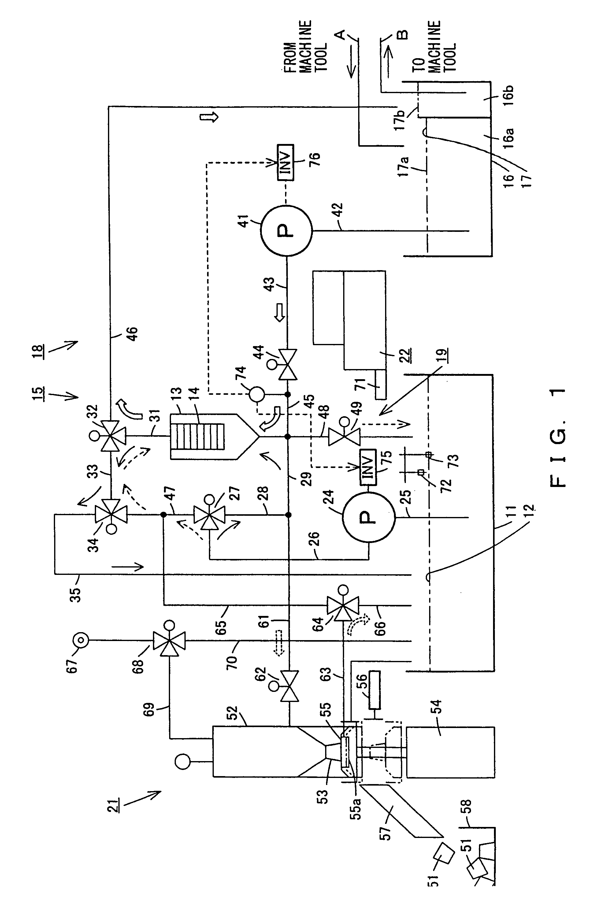
[0019] As shown in FIG. 1, provided are a filter auxiliary agent pre-coat circuit 15 which attaches and stacks a filter auxiliary agent contained in a filter auxiliary agent liquid 12 in a pre-coat tank 11 to the outer surface of a filter element 14 attached in a filter case 13 to form a filter auxiliary agent layer; a filter circuit 18 which removes sludge in a filter treatment liquid 17 in a main tank 16 by using the filter auxiliary agent layer of the filter element 14; a backwashing circuit 19 which breaks down the filter auxiliary agent layer and the sludge layer growing on the surface of the filter auxiliary agent layer, separates the filter auxiliary agent layer and the sludge layer by backwashing from the filter element 14 and circulates to the pre-coat tank 11; a recovery device 21 which takes out the filter auxiliary agent and the sludge to the exterior ...


PUM

PropertyMeasurementUnit
Pressureaaaaaaaaaa
Levelaaaaaaaaaa

Abstract

Using the filter auxiliary agent separated by backwashing from a filter element repeatedly and effectively, the consumption amount of a filter auxiliary agent and the generation of industrial waste can be suppressed. In a filter auxiliary agent pre-coat circuit, a filter auxiliary agent in a pre-coat tank is attached and stacked on a filter element in a filter case, and a filter auxiliary agent layer is formed. In a filter circuit, the filter auxiliary agent layer of the filter element removes sludge in the filter treatment liquid in a main tank. A backwashing circuit breaks down the filter auxiliary agent layer and a sludge layer, separates the filter auxiliary agent layer and the sludge layer by backwashing from the filter element, and circulates to the pre-coat tank. After repeating these steps a plurality of times, the filter auxiliary agent and sludge separated by backwashing are taken out to the exterior.

Description

INCORPORATION BY REFERENCE [0001] The present application claims priority under U.S.C. §119 to Japanese Patent Application No. 2004-290159. The content of the application is incorporated herein by reference in its entirety. FIELD OF THE INVENTION [0002] The present invention relates to a filtering method and filtering device by means of a filter element on which a filter auxiliary agent is attached and stacked. BACKGROUND OF THE INVENTION [0003] Conventionally, for example, as described in Japanese Laid-open Patent Publication No. 8-196821 (pp. 2-3, FIG. 1), a filter element has been known. In the filter element, a filter auxiliary agent layer is formed by attaching and stacking a filter auxiliary agent such as diatomaceous earth on the outer surface of a spring filter in which a slight filtering space is formed between adjacent rings by winding a wire having projection parts formed on the outer surface in a coil shape and interposing the projection parts between the adjacent rings....

Claims


Application Information

Patent Timeline
IPC IPC(8): B01D37/02
CPCB01D29/15B01D37/02B01D29/48B01D29/66B01D29/70B01D29/62B01D35/16
Inventor MIZUNO, YUJI
Owner NIKUNI
Why Eureka
Try Eureka