

Vibration isolator
a technology of vibration isolation and isolator, which is applied in the direction of shock absorbers, machine supports, mechanical equipment, etc., can solve the problems that the conventional vibration isolation device cannot meet the demand for weight and cost reduction, and the weight and cost reduction of automobile parts is increasing and increasing day by day, so as to achieve the effect of reducing the weight of the vibration isolation bas
- Summary
- Abstract
- Description
- Claims
- Application Information
AI Technical Summary
Benefits of technology
Problems solved by technology
Method used
Image

Examples
first embodiment
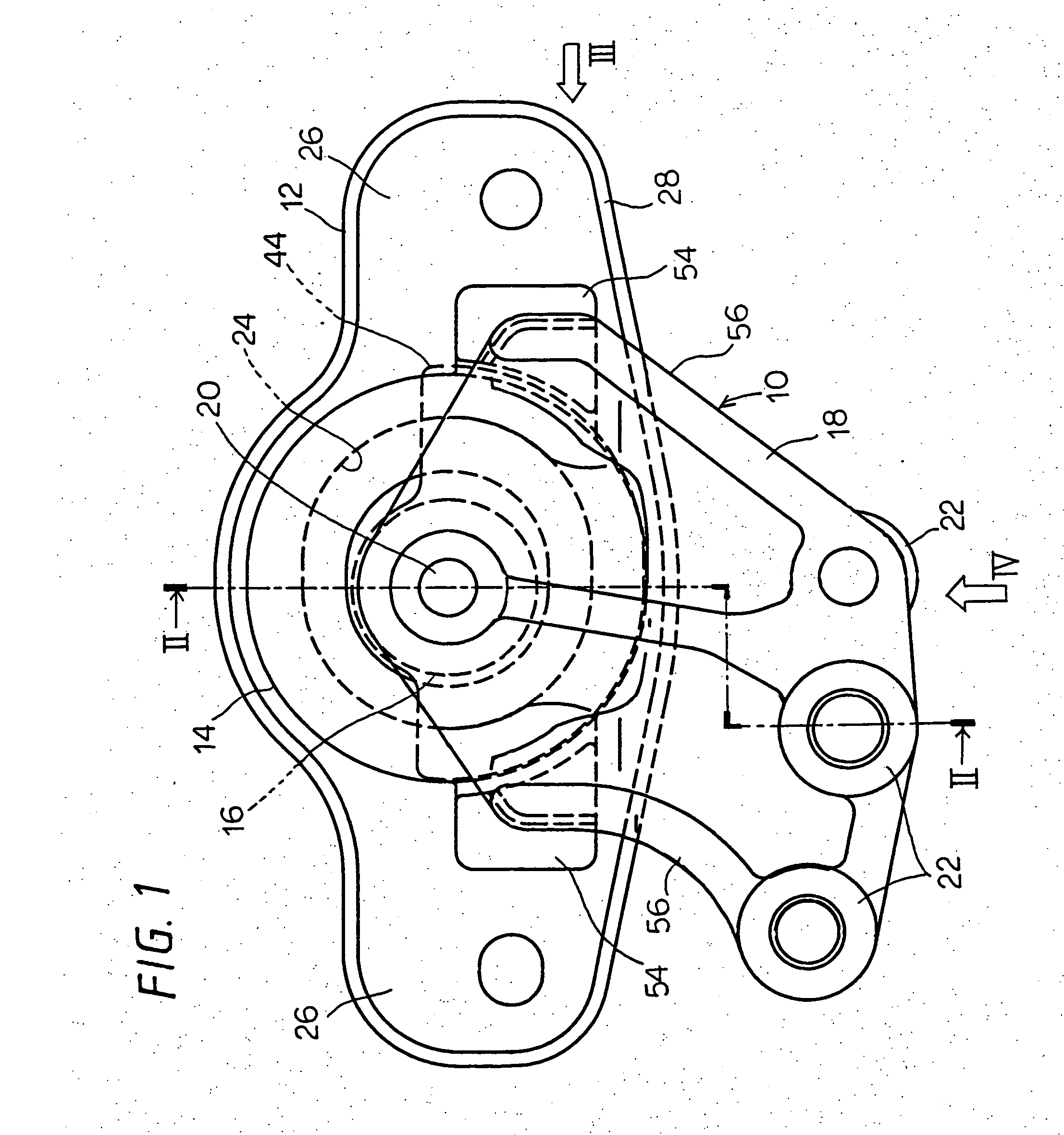
[0022] A first embodiment will be described with reference to FIGS. 1 to 4.
[0023] The vibration-isolating device in this embodiment is an engine mount supporting and bearing the right-hand part of an engine for FF (Front engine / Front wheel drive) vehicles to a vehicle body side member in a vibration-proof manner. In FIG. 1 the direction indicated by the arrow mark III is a front side of the vehicle.
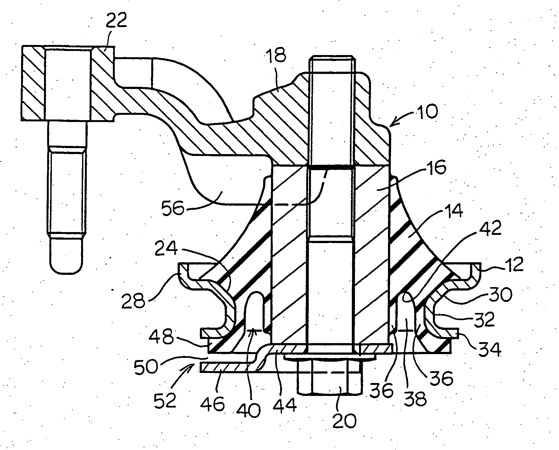
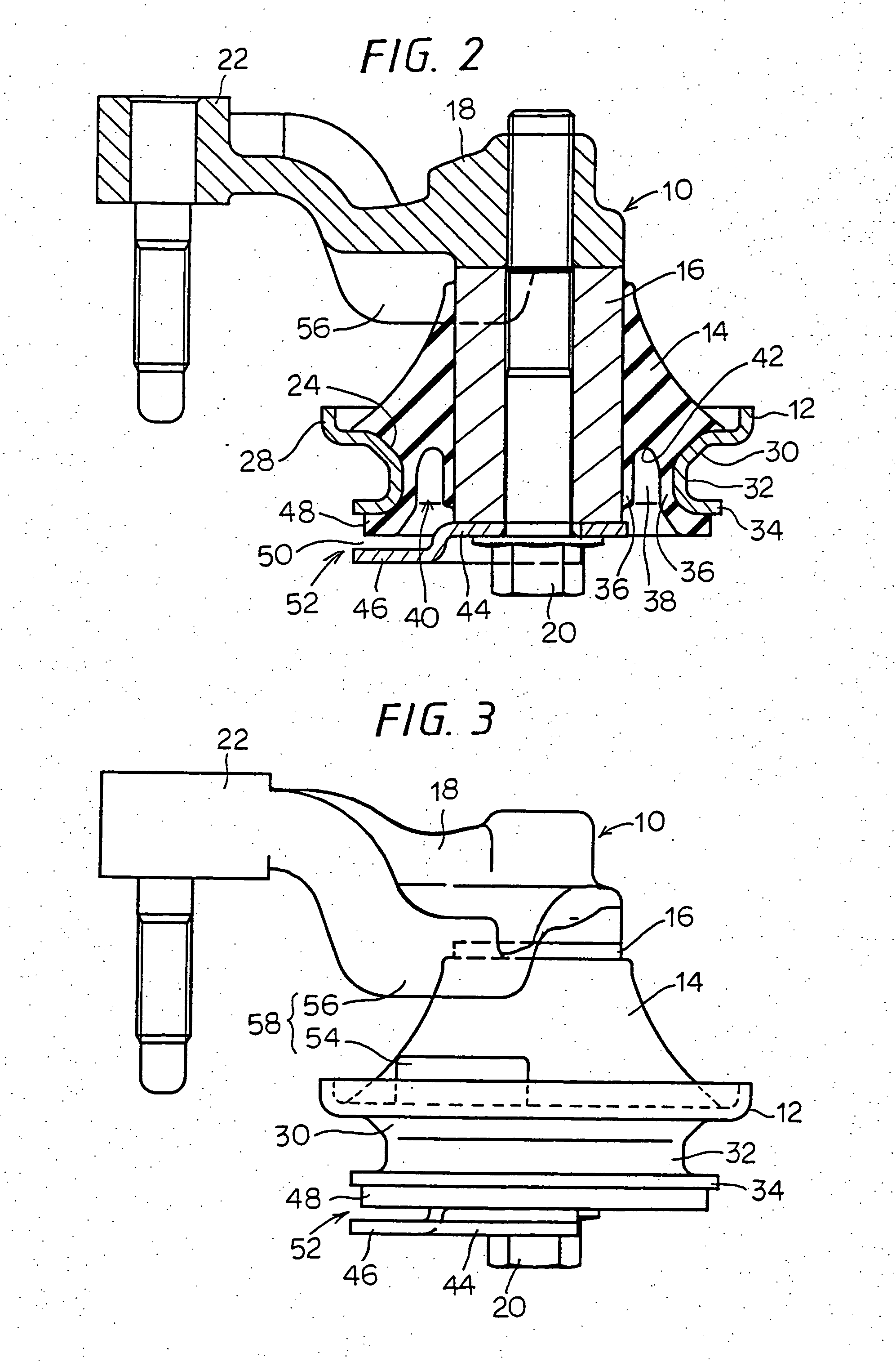
[0024] This vibration-isolating device comprises a first attachment member 10 made of metal to be fitted to an engine as a vibratory body, a second attachment member 12 made of metal to be fitted to a vehicle body member as a support body, and a vibration-isolating base 14 made of rubber-like elastomer interposed between the first attachment member 10 and the second attachment member 12 to connect the both in a vibration-proof manner.
[0025] The first attachment member 10 includes an inner cylinder 16 vertically disposed as a shank portion and a bracket 18 connecting the inner cylinder ...
second embodiment
[0040] A second embodiment as illustrated in FIG. 5 is different from the first embodiment described above in the construction of the inner cylinder 16 at the first attachment member 10, but the same as the first embodiment in other constructions, whose description therefore will be omitted.
[0041] In the second embodiment, for the inner cylinder 16 a press working product of a metal plate is employed. That is, the inner cylinder 16 is comprised of a cylindrical main body 60 surrounding the bolt 20 entered therethrough to be spaced apart a predetermined void 61, a bottom plate portion 62 which is an attachment face to the stopper fitting 44 disposed at the lower end of the cylindrical main body 60, and an outwardly facing, full-circumferential flange portion 64 which is an attachment face to the bracket 18 disposed at the upper end of the cylindrical main body 60, these three being fashioned integrally by press working of metal plate. The bottom plate portion 62 has a through-hole 6...
third embodiment
[0043] A third embodiment as shown in FIG. 6 is different from the foregoing first embodiment in the construction of the first attachment member 10 and the same as the first embodiment in other constructions, whose description will be omitted, accordingly.
[0044] In the third embodiment, the shank part of the first attachment member 10 is made up of two members: a first inner cylinder 70, on the upper side, connected through the vibration-isolating base 14 to the second attachment member 12 and a second inner cylinder 72 forming the first stopper part 40 together with the cylindrical portion 32 of the second attachment member 12.
[0045] The first inner cylinder 70 is fixed at its upper end to the underside of the bracket 18 by means of the bolt entered therethrough and terminated at its lower end with a height near the tapered face portion 30 of the second attachment member 12. The first inner cylinder 70 is set to be smaller in outside diameter at its lower end portion 74 whereas a...
PUM
 Abstract
Description
Claims
Application Information