Solenoid arrangement

a solenoid arrangement and solenoid technology, applied in the direction of electromagnets, electrical apparatus, dynamo-electric machines, etc., can solve the problems of high component cost and increase the weight, and achieve the effects of lowering the weight of the solenoid arrangement, high mechanical reliability, and lowering the weigh

Inactive Publication Date: 2006-04-06
ERMERT MICHAEL +1
View PDF2 Cites 17 Cited by
  • Summary
  • Abstract
  • Description
  • Claims
  • Application Information

AI Technical Summary

Benefits of technology

[0007] It is an object of the present invention to lower the weight of a solenoid arrangement or of a control member including such solenoid arrangement while providing a high mechanical reliability despite the lowered weight.
[0009] The configuration of the solenoid arrangement according to the invention enables the elimination of a heavy steel housing with fastening flange without the mechanical stability of the solenoid arrangement being compromised.
[0013] In this connection, it is particularly favorable when the plunger, for example, connected by pressing (press-fit) to the armature and acting on a valve slide, is provided with a ball at the end projecting from the solenoid arrangement and facing the valve slide or a similar functional part because, in this way, possible wear caused not only by rotational movement of the valve slide but also by a displacement of the axial positions of the solenoid arrangement and of the valve slide relative to one another can be minimized. When using a steel ball, the wear is significantly minimized because its surface hardness can be high.
[0014] Sealing of the armature and of the plunger can be ensured by means of a sleeve closed off at one end, wherein the sleeve is welded axially onto an area of the cup-shaped housing part. By means of the axial weld connection, the guide member surrounded by the magnetizable sleeve and the cup-shaped housing part can radially adjoin one another and, in this way, continuous magnetic flux is ensured.
[0015] In particular, such a solenoid arrangement can be a component of a control member which comprises additionally one or several members to be adjusted, for example, a valve slide. A particularly suitable application of such a control device is the use as a camshaft adjuster, for example, when the valve slide controls an adjusting motor for a camshaft. By separating the solenoid arrangement from the valve effecting the adjustment, the length of the control member can be shortened in comparison to prior art camshaft adjusters in which the armature and the valve form a modular unit. The requirements with regard to support and positional adjustment are significantly reduced.

Problems solved by technology

The steel housing however increases the weight greatly and causes relatively high component costs.

Method used


Image

  • Solenoid arrangement
  • Solenoid arrangement
  • Solenoid arrangement

Examples


Embodiment Construction

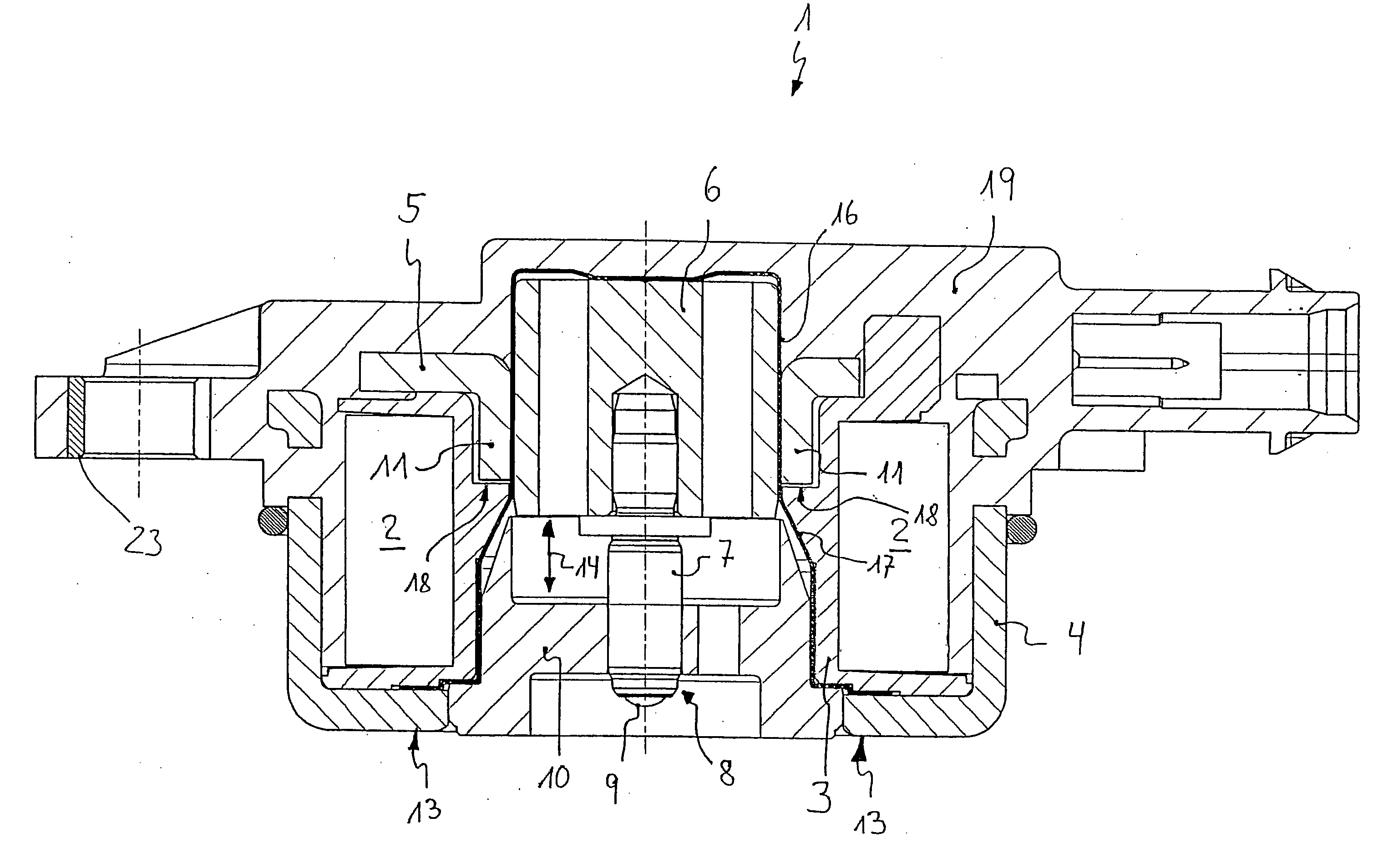
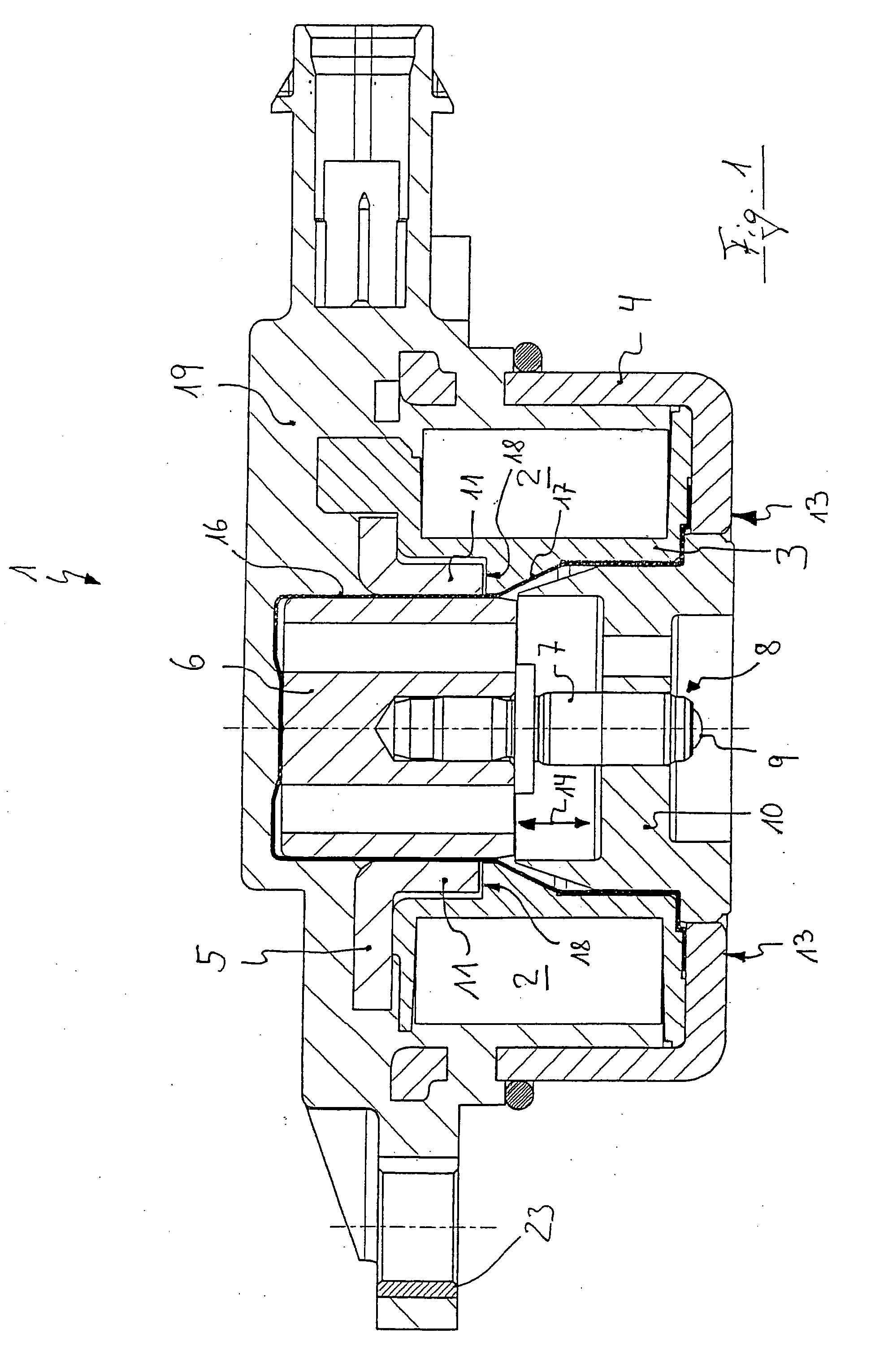
[0022]FIG. 1 illustrates a solenoid arrangement 1 according to the invention that operates, for example, proportionally magnetically. It comprises an excitation coil 2 which is secured on a coil support 3, for example, made of plastic material. The coil support 3 and the excitation coil 2 are positioned in a magnetizable cup-shaped housing part 4. A substantially plate-shaped magnetizable yoke5 forms an axial closure of the open cup-shaped housing part 4. At the center of the excitation coil 2 an axially moveable armature 6 is supported. The armature 6 supports centrally a plunger 7 which is the actual switching element for further functional parts, for example, a valve slide. The leading end 8 of the plunger 7 projecting out of the solenoid arrangement is provided with a ball 9. The plunger 7 is axially movably held in a fixedly mounted or fitted guide member 10. The guide member 10 is cone-shaped and secured axially underneath and at a spacing to the axially extending flange areas...


PUM

PropertyMeasurementUnit
currentaaaaaaaaaa
magnetizableaaaaaaaaaa
areaaaaaaaaaaa

Abstract

A solenoid arrangement has at least one excitation coil and an armature arranged concentrically relative to the excitation coil and axially movable when the at least one excitation coil is supplied with current. A magnetizable cup-shaped housing part open at a first axial side is provided, wherein the at least one excitation coil is at least partially surrounded by the magnetizable cup-shaped housing part. A magnetizable yoke covers the first axial side for closing the magnetic circuit. A housing cover covering the solenoid arrangement is formed of plastic material, wherein the plastic material has at least one attachment flange for mounting the solenoid arrangement on other parts.

Description

CROSS-REFERENCE TO RELATED APPLICATIONS [0001] This is a Divisional Application of U.S. patent application Ser. No. 10 / 647,129.BACKGROUND OF THE INVENTION [0002] 1. Field of the Invention [0003] The invention relates to a solenoid arrangement comprising at least one excitation coil and an armature arranged concentrically relative to the excitation coil and axially movable when the excitation coil is supplied with current, wherein the excitation coil is at least partially surrounded by a magnetizable cup-shaped housing part open at one axial side and wherein the open side can be covered for further closing the magnetic circuit by a magnetizable yoke, and wherein the solenoid arrangement is closed off by a housing cover. The invention also relates to a control member for affecting fluid flow. The invention moreover relates to a method for producing a solenoid arrangement comprising at least one excitation coil and an armature arranged concentrically relative to the excitation coil and...

Claims


Application Information

Patent Timeline
Patent Type & Authority Applications(United States)
IPC IPC(8): H02K41/00F01L1/344H01F7/127H01F7/128H01F7/16
CPCF01L1/344F01L2001/34426F01L2001/3443F01L2101/00H01F7/127H01F7/128H01F7/1607F01L2301/00
Inventor ERMERT, MICHAELHAGE, BERND
Owner ERMERT MICHAEL
Why Eureka
Try Eureka