
Illumination system using multiple light emitting diodes

Inactive Publication Date: 2006-04-06
3M INNOVATIVE PROPERTIES CO
View PDF16 Cites 31 Cited by
  • Summary
  • Abstract
  • Description
  • Claims
  • Application Information

AI Technical Summary

Benefits of technology

[0006] The above summary of the present invention is not intended to describe each illustrated embodiment or every implementation of the present invention. The figures and the following detailed description more particularly exemplify these embodiments.

Problems solved by technology

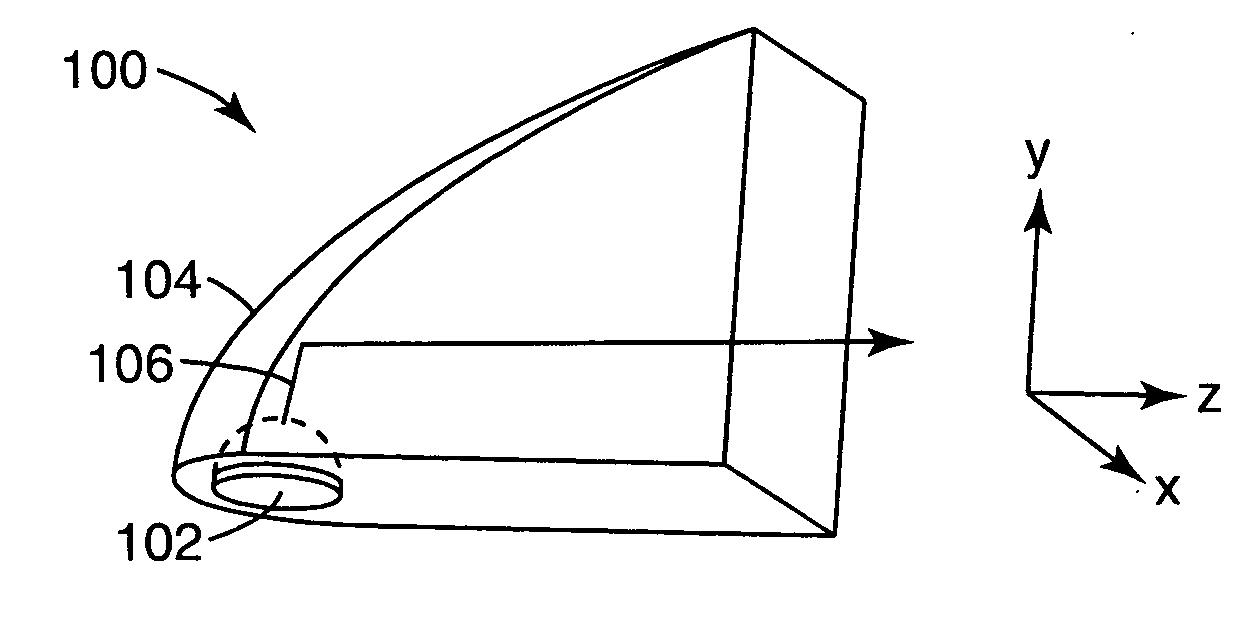
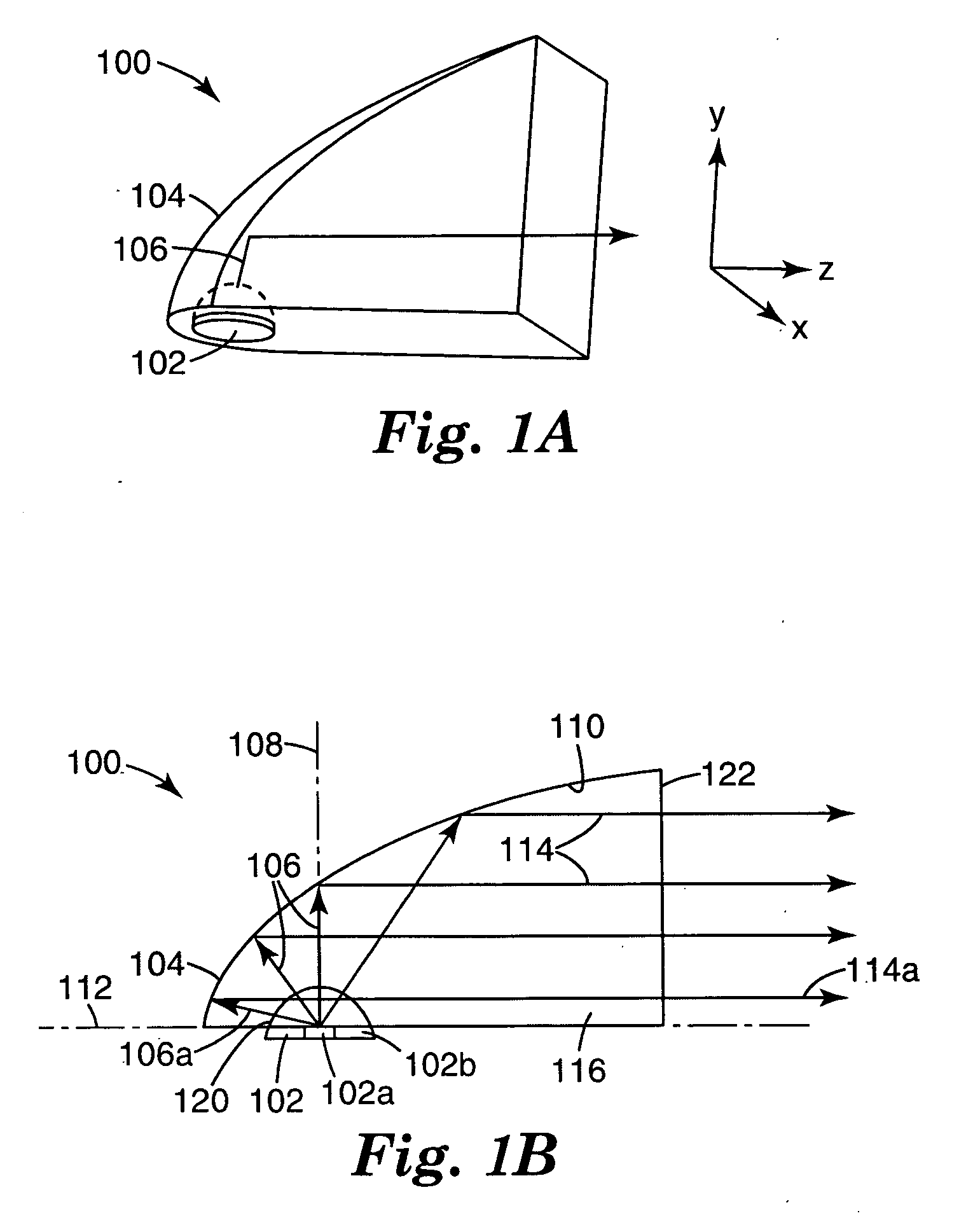
The large emission angle for the LED light introduces system design issues related to collecting and directing the light when the LED is used as a light source.

Method used


Image

  • Illumination system using multiple light emitting diodes
  • Illumination system using multiple light emitting diodes
  • Illumination system using multiple light emitting diodes

Examples


example 1

[0058] An exemplary embodiment of an illumination module 800 used in a sub-unit to generate beam 1 is schematically illustrated in FIG. 8A. The module 800 includes an LED 802, a paraboloidal reflector 804, and an output surface 806. The paraboloidal reflector 804 has a value of R=10 mm, a depth, d=36 mm and the output surface is square with a height and width, h and w, equal to 24 mm. The output surface 806 of the module 800 is flat. The desired angular aperture from the sub-unit is ±2° vertically and ±5° horizontally. Accordingly, the amount of light, P, generated by a single illumination module into this angular aperture can be calculated as:

P=Po×CE×L1×L2  (1)

where P0 is the amount of light output from the LED, CE is the geometrical light collection efficiency, L1 is reflectivity of the reflector and L2 is the transmission through the output surface of the module. The value of CE, for this particular angular aperture can be calculated to be 42.1%. The value of L1, the reflectiv...

example 2

[0060] An exemplary embodiment of an illumination module 900 used in a sub-unit to generate beam 2 is schematically illustrated in FIG. 9A. The module 900 includes an LED 902, a paraboloidal reflector 904, and an output surface 906. The paraboloidal reflector 904 has a value of R=9 mm, a depth of d=30.5 mm. The output surface 906 is square with a height and width, h and w, equal to 20 mm. The output surface 906 of the module 900 has a cylindrical surface with a radius of curvature equal to 19 mm. The use of a curved output surface 906 may increase the spread of light in the horizontal direction. The desired angular aperture from the sub-unit is ±5° vertically and ±35° horizontally. The geometrical collection efficiency, CE, into this angular aperture can be obtained from FIG. 6C as about 79%. The amount of light, P, generated by a single illumination module into this angular aperture can be calculated using expression (1) as 60.1 Lumens, where the values of L1 and L2 are as given in...


PUM


Abstract

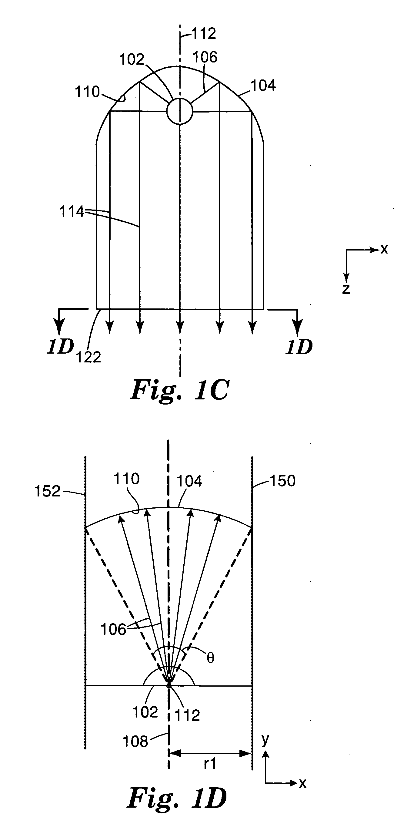
An illumination system is based on multiple light emitting diodes (LEDs), arranged in a row, to side-illuminate respective reflectors. The illumination system is particularly useful as a vehicle headlamp. In some embodiments, the reflectors may be curved, for example paraboloidal, to collect the light, but truncated in the direction along the row: this allows for closer packing of the LEDs. In other embodiments, the different reflectors point in different directions so as to spread the combined light beams across the driver's field of view. In other embodiments, the reflectors for the different LEDs may be formed on a single molded body.

Description

FIELD OF THE INVENTION [0001] The invention relates to optical systems, and more particularly to an illumination system, for example a vehicle headlight, that uses a number of light emitting diodes as the sources of light. BACKGROUND [0002] Light emitting diodes (LEDs) are devices that emit light from a semiconductor junction. The light is emitted from an LED over a wide range of angles via the combination of carriers at the junction. The large emission angle for the LED light introduces system design issues related to collecting and directing the light when the LED is used as a light source. On the other hand, the small size, long life and high optical efficiency, typically in excess of 50% of electrical energy converted to optical energy, make the LED attractive as a light source for directed illumination systems, such as vehicle headlights. There is a need, therefore, for an approach to collecting and directing LED light with high efficiency while maintaining small size and low c...

Claims


Application Information

Patent Timeline
Patent Type & Authority Applications(United States)
IPC IPC(8): B60Q1/26
CPCF21S2/005F21S48/1159F21S48/1163F21V7/0091F21V7/04F21V7/06F21Y2101/02F21Y2115/10F21S41/148F21S41/153F21S41/155
Inventor MAGARILL, SIMON
Owner 3M INNOVATIVE PROPERTIES CO
Features
  • Generate Ideas
  • Intellectual Property
  • Life Sciences
  • Materials
  • Tech Scout
  • Unparalleled Data Quality
  • Higher Quality Content
  • 60% Fewer Hallucinations
Learn More