
Rotary optical switch

a technology of optical switch and rotary switch, which is applied in the direction of optical radiation measurement, instruments, spectrometry/spectrophotometry/monochromators, etc., can solve the problems of limit to the rate of interrogation and also the number of discrete elements

Inactive Publication Date: 2006-04-06
OPTICAL ONCOLOGY
View PDF15 Cites 19 Cited by
  • Summary
  • Abstract
  • Description
  • Claims
  • Application Information

AI Technical Summary

Problems solved by technology

In such a case, there are limits to the rate of interrogation, and also to the number of discrete elements that can be used for interrogations.

Method used


Image

  • Rotary optical switch
  • Rotary optical switch
  • Rotary optical switch

Examples


Embodiment Construction

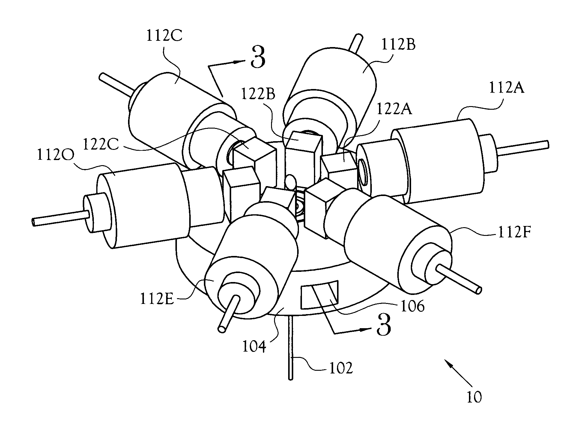
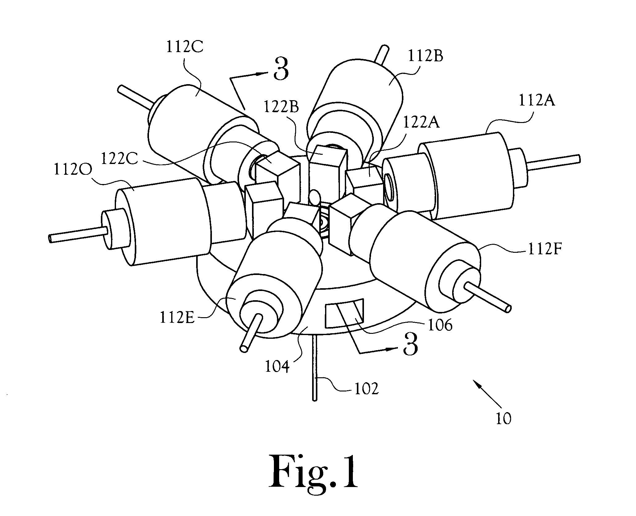
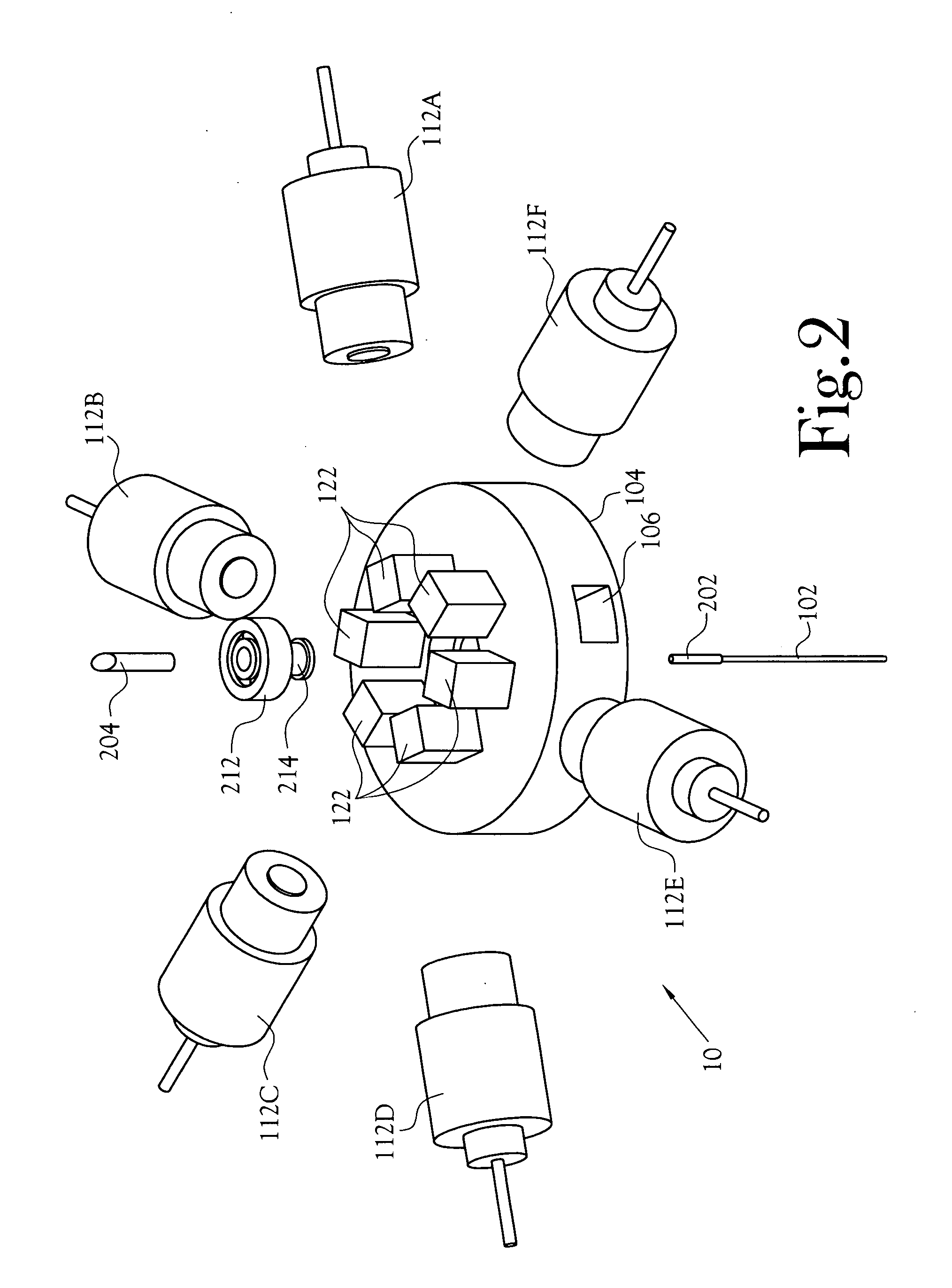
[0016] An apparatus for directing a light path sequentially between multiple positions is disclosed. The optical switch is generally identified as item 10 in the drawings. The illustrated embodiments of the rotary optical switch 10 show the use of filters 122 in the light path.

[0017]FIG. 1 illustrates a perspective view of one embodiment of a rotary optical switch 10. An optical fiber 102 enters along the axis of a switch body, or support member, 104 that has photo detectors 112 mounted radially along the circumference of the body 104. Adjacent the optical input port of each photo detector 112A, B, C, D, E, and F is a filter 122A, B, C, D, E, and F. An optical signal passes through the optical fiber 102 and into a rotating prism 204 that directs the optical signal sequentially through each filter 122 and to each optical sensor 112. The filters 122 and photodetectors 112 are optical elements that act upon or respond to a light beam.

[0018] In one embodiment, the switch body 104 is c...


PUM


Abstract

An apparatus for directing a light path sequentially between multiple positions. A rotary switch rotates a light beam from a prism relative to a plurality of optical elements arranged radially on a switch body. In one embodiment, a prism rotates in the switch body, causing the light beam to sweep through the optical elements. In another embodiment, the switch body rotates about a prism transmitting the light beam. In various embodiments, the optical elements include a photodetector, a filter and a photodetector pair, a reflector, and a filter and a reflector.

Description

CROSS-REFERENCE TO RELATED APPLICATIONS [0001] This application claims the benefit of Provisional Application Ser. No. 60 / 589,454, filed Jul. 20, 2004.STATEMENT REGARDING FEDERALLY SPONSORED RESEARCH OR DEVELOPMENT [0002] Not Applicable BACKGROUND OF THE INVENTION [0003] 1. Field of Invention [0004] This invention pertains to an optical switch. More particularly, this invention pertains to an optical switch that directs a light path sequentially between multiple positions radially surrounding a rotating optical member. [0005] 2. Description of the Related Art [0006] In prior art optical switching applications the switch moves from one stable position into a second or third or larger number of stable positions, such that there is a reciprocal movement, or change in inertial position, either kinetically or electro-optically. In such a case, there are limits to the rate of interrogation, and also to the number of discrete elements that can be used for interrogations. BRIEF SUMMARY OF T...

Claims


Application Information

Patent Timeline
Patent Type & Authority Applications(United States)
IPC IPC(8): G02B6/26
CPCG02B6/29361G02B6/29395G02B6/3512G02B6/352G02B6/3524G02B6/3528G02B6/3532G02B6/3548G02B6/3552G02B6/3558G02B6/3574G02B6/3582G02B6/3588G02B6/3598G02B6/4246G01J3/12G01J3/36G01J2003/1213G01J2003/1221G01J3/0218
Inventor TEKIPPE, VINCENT J.GUYNN, ROYCARBERRY, JOHN
Owner OPTICAL ONCOLOGY
Features
  • Generate Ideas
  • Intellectual Property
  • Life Sciences
  • Materials
  • Tech Scout
  • Unparalleled Data Quality
  • Higher Quality Content
  • 60% Fewer Hallucinations
Learn More