Process cartridge and electrophotographic image forming apparatus
a technology of electrophotographic image and process cartridge, which is applied in the direction of electrographic process, optics, instruments, etc., can solve the problems of moment adversely affecting the positional accuracy of the developing roller, and achieve the effect of less deformation and less bending momen
- Summary
- Abstract
- Description
- Claims
- Application Information
AI Technical Summary
Benefits of technology
Problems solved by technology
Method used
Image
Examples
first embodiment
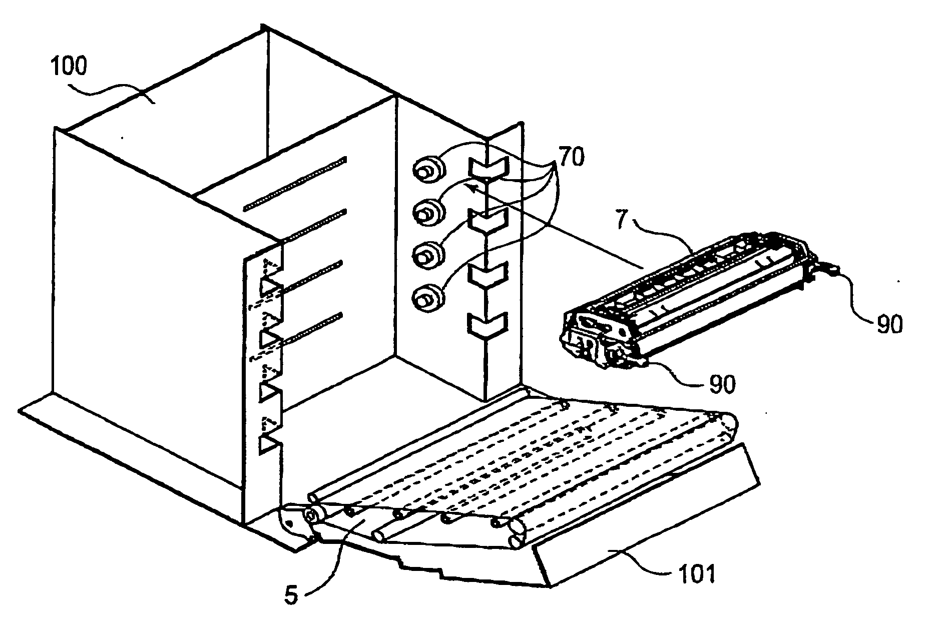
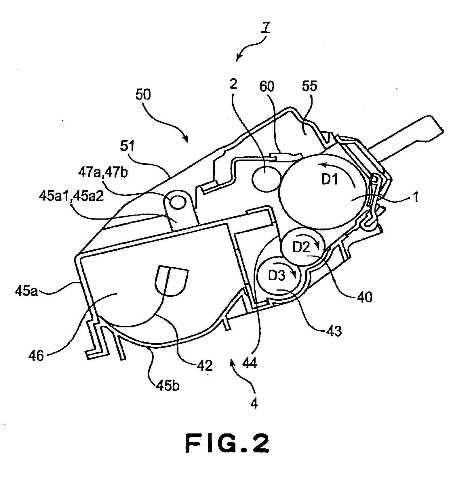
[0028] The description will be made as to a developing unit, a process cartridge and an electrophotographic image forming apparatus according to an embodiment of the present invention.
(General Arrangement of Image Forming Apparatus)
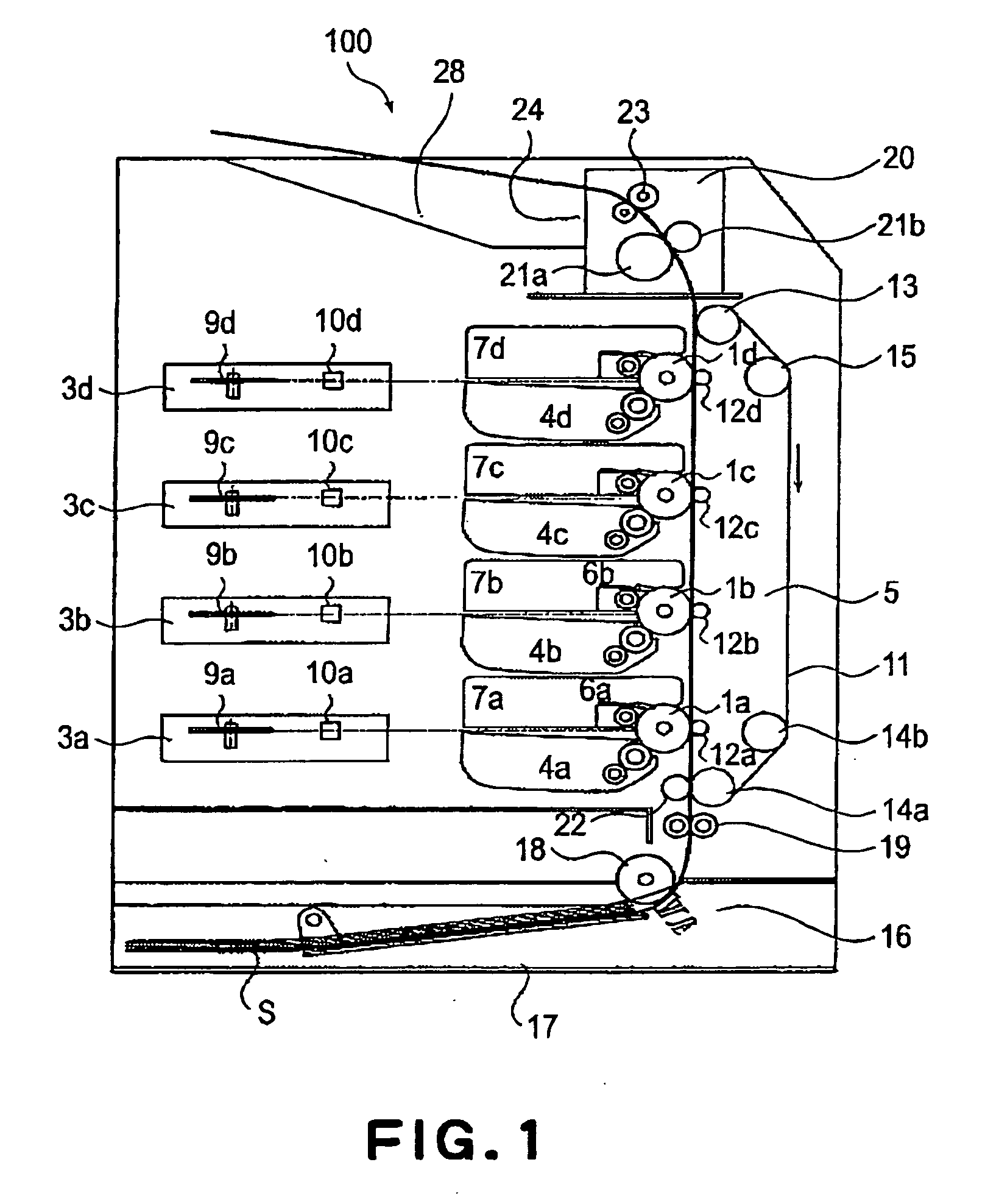
[0029] Referring to FIG. 1, the description will first be made as to the general arrangement of the multi-color image forming apparatus. FIG. 1 is a longitudinal sectional view illustrating a general arrangement of a full-color laser beam printer 100 which is an example of a multi-color image forming apparatus.
[0030] The multi-color image forming apparatus 100 shown in this Figure includes four photosensitive drums 1a, 1b, 1c, 1d which are arranged substantially vertically. The photosensitive drum 1 is rotated in the counterclockwise direction in the Figure by a driving means (unshown). Around the photosensitive drum 1, there are provided charging means 2 (2a, 2b, 2c, 2d) for electrically charging the associated photosensitive drum 1 to a uniform pote...
second embodiment
[0070] The mounting structure of the developing device is frame 45 relative to the cleaning frame 51 may be as shown in FIG. 12. Here, a position, in the longitudinal direction of the cartridge 7, of an arm 45a1 having the hole 52a for penetration of the pin 47 is seen in the direction which is perpendicular to the longitudinal direction of the cartridge 7 and which passes through the cartridge positioning portion 51a (direction V3 in FIGS. 11 and 12). Then, the arm 45a1 which is an engaging portion relative to the pin 47 is at a position overlapping with the second cartridge positioning portion 51a.
[0071] When they are seen in the direction V1 in FIG. 11, the structure is as follows. Namely, the position of the arm 45a1 having the hole 52a for penetration of the pin 47 overlaps with an extension line EL1 of the force Y received by the driving input gear 76 with respect to the longitudinal direction of the cartridge 7. Similarly, to the structure in FIG. 10, an extension EL1 of the...
PUM
 Abstract
Description
Claims
Application Information
 - R&D
- Intellectual Property
- Life Sciences
- Materials
- Tech Scout
- Unparalleled Data Quality
- Higher Quality Content
- 60% Fewer Hallucinations
Browse by: Latest US Patents, China's latest patents, Technical Efficacy Thesaurus, Application Domain, Technology Topic, Popular Technical Reports.
© 2025 PatSnap. All rights reserved.Legal|Privacy policy|Modern Slavery Act Transparency Statement|Sitemap|About US| Contact US: help@patsnap.com


