Miter dowel jig

Inactive Publication Date: 2006-04-06
JOHNSON ERIC
View PDF7 Cites 2 Cited by
  • Summary
  • Abstract
  • Description
  • Claims
  • Application Information

AI Technical Summary

Benefits of technology

[0005] The present invention provides a new and improved fixture for the method of preparing a mitered joint to be constructed with dowels. This particular jig's innovation is do to the fact that it is composed of precisely drilled holes that allow the exact drilling and placement of perfectly aligned holes in materials that are used in the making of a mitered join

Problems solved by technology

As far as known, there appears to be no prior art patent dealing with an assembly that is

Method used


Image

  • Miter dowel jig
  • Miter dowel jig
  • Miter dowel jig

Examples


Embodiment Construction

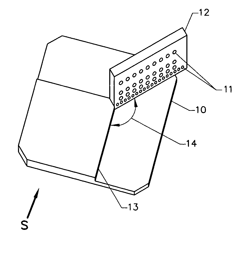
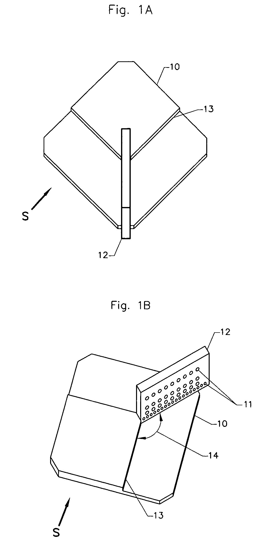
[0011] In the drawings (FIG. 1A) and (FIG. 1B) the letter S designates generally a new and improved miter dowel jig according to the present invention. The dowel jig S (FIG. 1A) consists of a support plate 10 made of various materials and plate 12 made of various materials. Support plate 10 consists of a flat plate with a stop 13 to provide support and exact location of materials to be doweled and mitered. Boring plate 12 (FIG. 1B) consists of a number of holes 11 that are of various diameter sizes. Plate 12 is attached to plate 10 as in (FIG. 1A) such that an angle 14 (FIG. 1B) is formed with stop 13 and plate 12. The angle 14 is the angle of the designated miter joint.

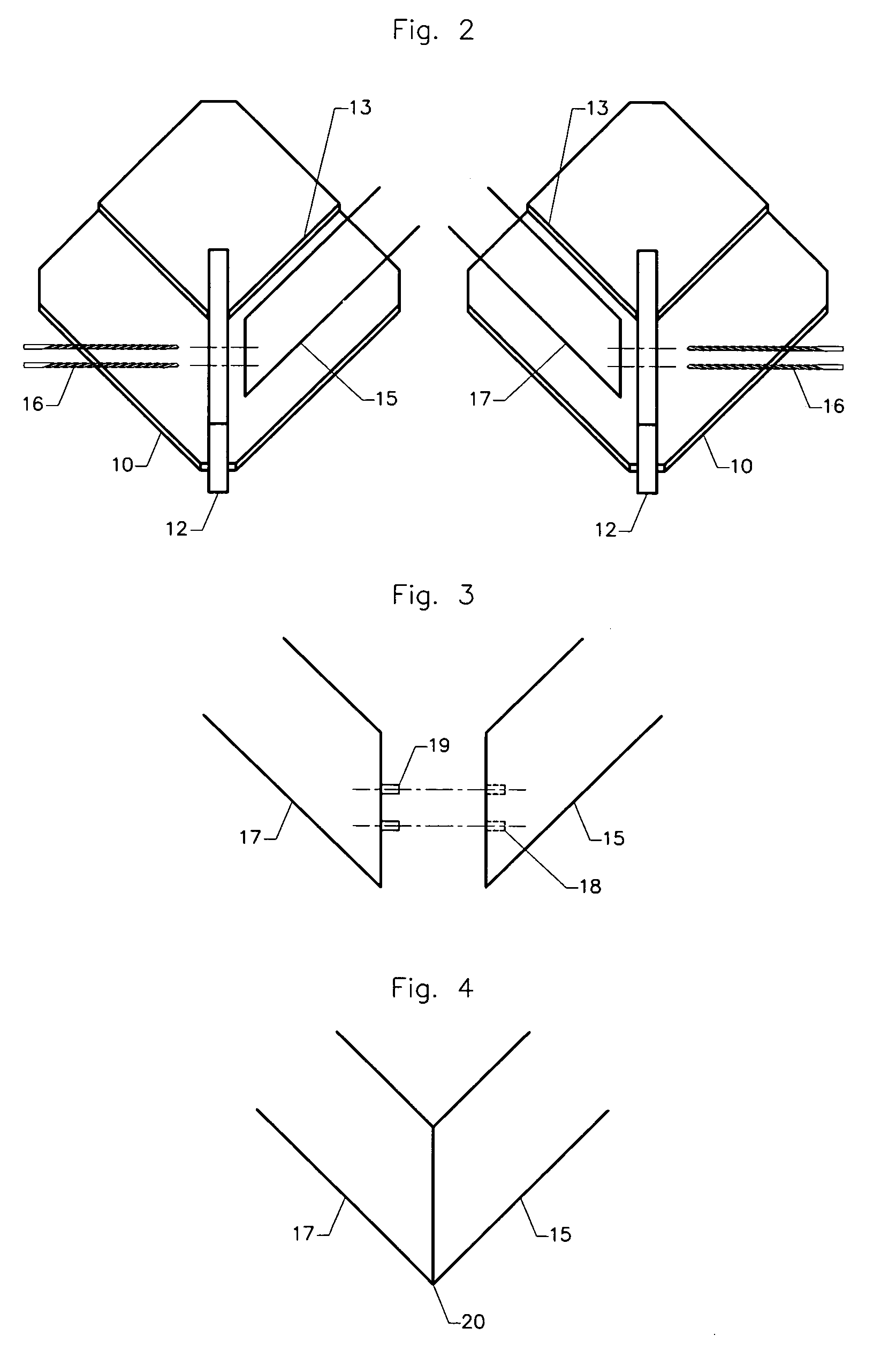
[0012] The miter dowel process is effected with the invention S (FIG. 2) by placing a piece of designated material 15 against the stop 13 and against plate 12. A drill 16 (FIG. 2) is then used to drill or bore a hole of the selected diameter through the hole 11 (FIG. 1B) in plate 12 into the material 15. A second pi...


PUM

PropertyMeasurementUnit
Angleaaaaaaaaaa
Angleaaaaaaaaaa

Abstract

A miter dowel jig comprised of two plates that when assembled form a complete unit. This unit may be used as a jig fixture to drill holes in various materials for the preparation of the placement of dowels in a mitered joint of various angles.

Description

BACKGROUND OF THE INVENTION: [0001] 1) Field of Invention [0002] The present invention relates to a jig in making and assembly of a doweled miter joint such as corner joints in picture frame moldings, window moldings, architectural moldings, mirror frames and the like. [0003] 2) Description of Prior Art [0004] As far as known, there appears to be no prior art patent dealing with an assembly that is used as a miter jig to aid in the fabrication and placement of dowels in a mitered joint. SUMMARY OF INVENTION [0005] The present invention provides a new and improved fixture for the method of preparing a mitered joint to be constructed with dowels. This particular jig's innovation is do to the fact that it is composed of precisely drilled holes that allow the exact drilling and placement of perfectly aligned holes in materials that are used in the making of a mitered joint. The jig allows for the perfect alignment of dowel holes in two pieces of material that will be used to construct a...

Claims


Application Information

Patent Timeline
IPC IPC(8): B23B49/02
CPCY10T408/567B23B49/02
Inventor JOHNSON, ERIC
Owner JOHNSON ERIC
Why Eureka
Try Eureka