Apparatus and method for composite tape profile cutting

a composite tape and tape profile technology, applied in the field of composite structure manufacturing, can solve the problems of reducing the strength of the resulting composite member and reducing the strength, and achieve the effect of reducing or eliminating the occurrence of laps or gaps

Inactive Publication Date: 2006-04-06
THE BOEING CO
View PDF79 Cites 74 Cited by
  • Summary
  • Abstract
  • Description
  • Claims
  • Application Information

AI Technical Summary

Benefits of technology

[0008] The present invention provides a composite member and an associated method and apparatus for forming the member. The composite member is form...

Problems solved by technology

However, if the surface of the mandrel defines a complex contour, the tapes disposed by the machine may define laps or gaps.
Laps and gaps can decrease the strength of the resultin...

Method used


Image

  • Apparatus and method for composite tape profile cutting
  • Apparatus and method for composite tape profile cutting
  • Apparatus and method for composite tape profile cutting

Examples


Embodiment Construction

[0023] The present invention now will be described more fully with reference to the accompanying drawings, in which some, but not all embodiments of the invention are shown. This invention may be embodied in many different forms and should not be construed as limited to the embodiments set forth. Like numbers refer to like elements throughout.

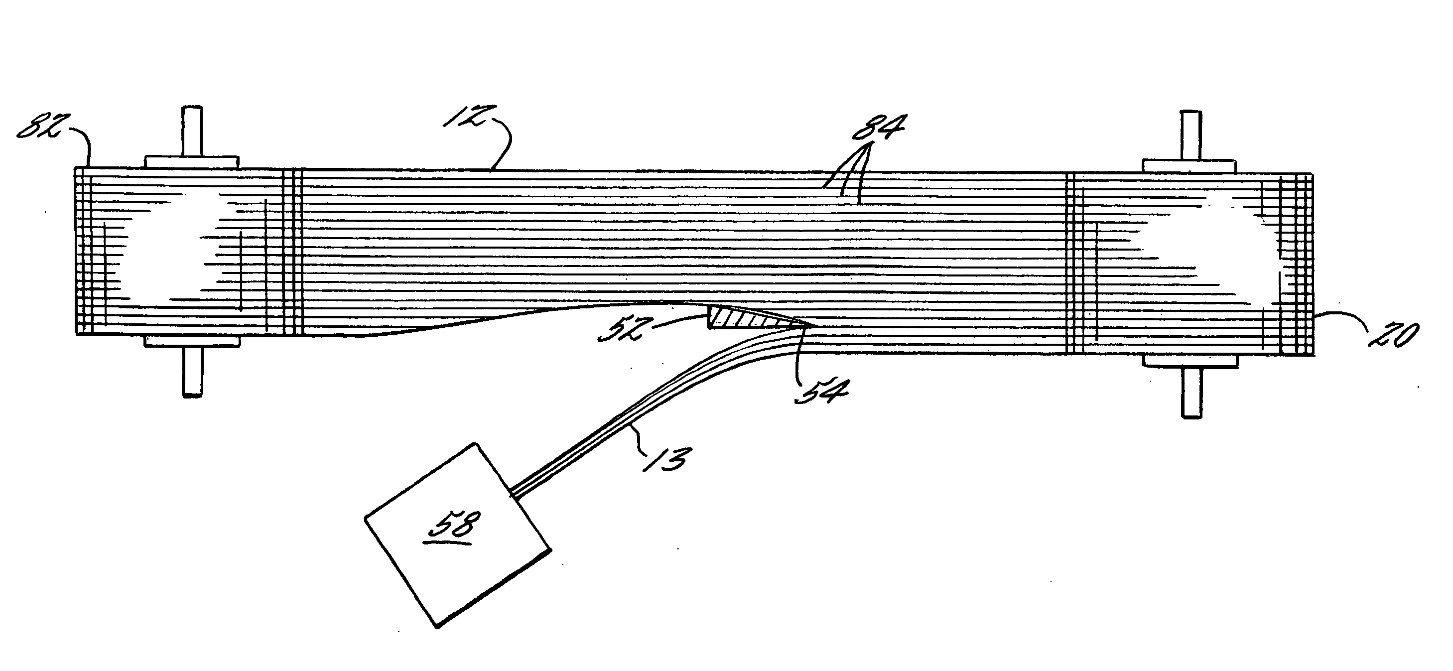
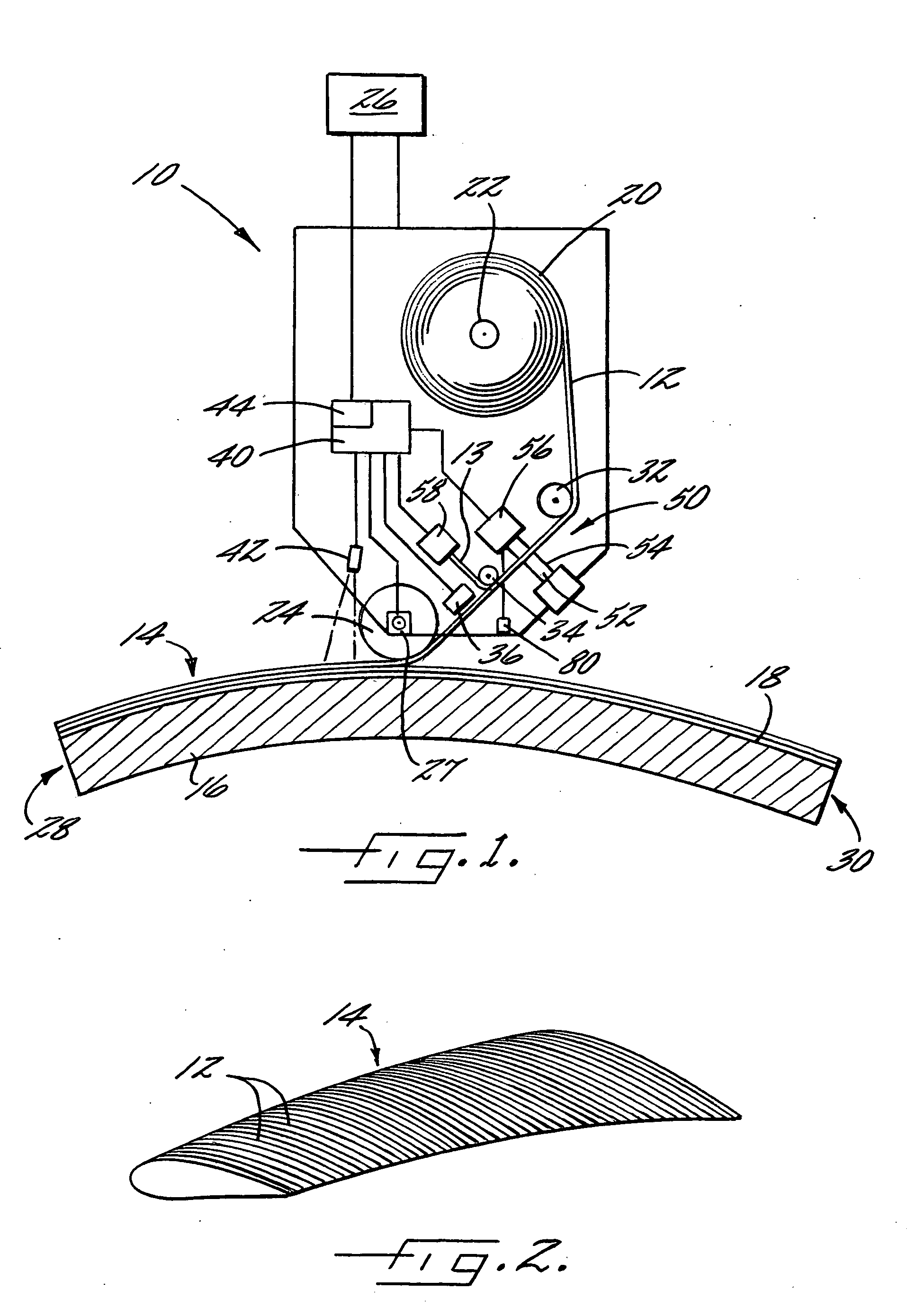
[0024]FIG. 1 schematically illustrates an apparatus 10 for disposing an elongate tape 12 during formation of a composite member 14. The apparatus 10 can be used to form composite members 14 of a variety of materials and having various configurations. In particular, the apparatus 10 can be used to dispose one or more elongate tape 12 (or “tow”) that includes a reinforcement material disposed in a matrix material. Typically, the reinforcement material is a plurality of fibrous members such as fibers, strands, braids, woven or nonwoven mats, and the like of materials such as fiberglass, metal, minerals, conductive or nonconductive graphite or car...


PUM

PropertyMeasurementUnit
Shapeaaaaaaaaaa
Widthaaaaaaaaaa
Configurationaaaaaaaaaa

Abstract

A composite member and an associated method and apparatus for forming the composite member are provided. The composite member is formed of a plurality of elongate tapes. Side edges of some or all of the tapes can be trimmed to reduce or eliminate the occurrence of laps or gaps between the adjacent tapes.

Description

CROSS-REFERENCES TO RELATED APPLICATIONS [0001] This application is a continuation-in-part of copending U.S. patent application Ser. No. 60 / 615,895, filed on Oct. 5, 2004, which is hereby incorporated herein in its entirety by reference.BACKGROUND OF THE INVENTION [0002] 1) Field of the Invention [0003] The present invention relates to the manufacture of composite structures and, more specifically, to an apparatus and associated method for trimming elongate tapes and disposing the tapes in a desired configuration to form the composite structures. [0004] 2) Description of Related Art [0005] Composite members are typically formed of a reinforcement material that is disposed in a matrix material. For example, the reinforcement material can be a fibrous material such as graphite, and the matrix material can be a resinous polymer material. According to one conventional manufacturing method, the composite material is disposed in the desired shape of the composite member by laying a plural...

Claims


Application Information

Patent Timeline
IPC IPC(8): B32B1/00
CPCB29C70/386Y10T428/24628B29C70/545
Inventor HOGG, MERRILL W.
Owner THE BOEING CO
Why Eureka
Try Eureka