
Integrated lance and strip for analyte measurement

Inactive Publication Date: 2006-04-06
LIFESCAN IP HLDG LLC
View PDF52 Cites 7 Cited by
  • Summary
  • Abstract
  • Description
  • Claims
  • Application Information

AI Technical Summary

Benefits of technology

The design effectively holds the incision open, prevents fluid blockage, and ensures efficient fluid flow into the channel, improving the reliability and ease of use in integrated skin lancing and fluid analysis systems.

Problems solved by technology

However, such solid needles generally rely on the size of the incision to ensure that enough bodily fluids are expressed and are not used to facilitate the flow of fluids to the testing apparatus.

Method used


Image

  • Integrated lance and strip for analyte measurement
  • Integrated lance and strip for analyte measurement
  • Integrated lance and strip for analyte measurement

Examples


Embodiment Construction

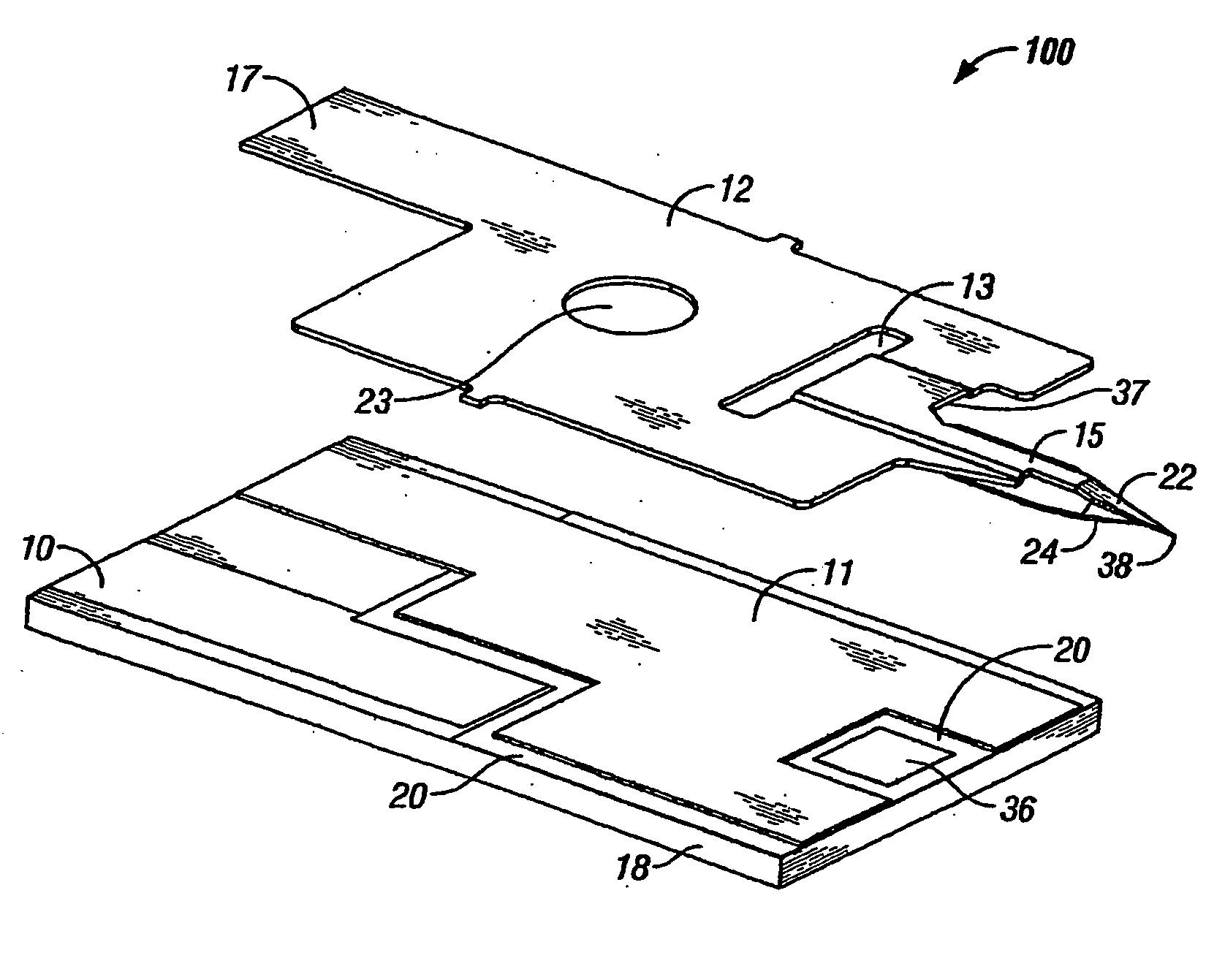
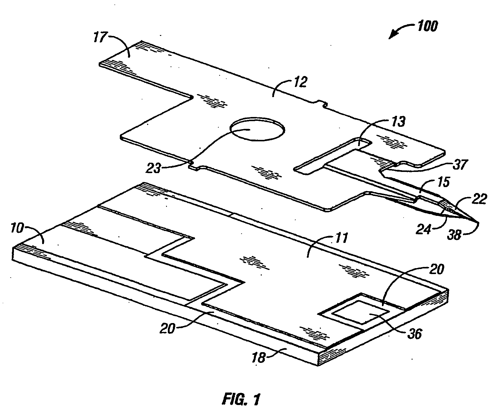
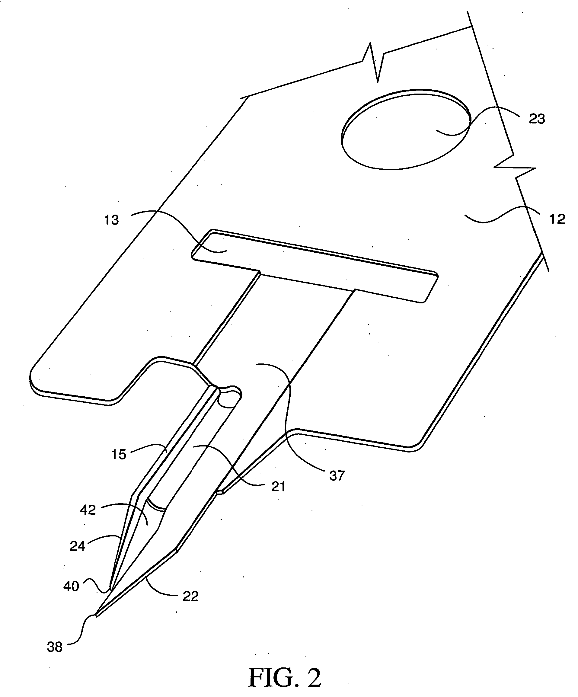
[0015]FIG. 1 is a perspective view of lance 15 and sensor strip 100 according to the present invention. In FIG. 1, lance 15 is connected to sensor strip 100. Sensor strip 100 may be, for example, a glucose sensor strip which uses electrochemistry to measure the amount of glucose in a bodily fluid, such as, for example, blood or interstitial fluid. Additionally, sensor strip 100 may be, for example, a coagulation sensor which measures a physical characteristic of a body fluid such as viscosity, capacitance, resistance, and the like. In FIG. 1, lance 15 further includes lancing element 22 and separation element 24. Sensor strip 100 further includes first electrode contact 10, adhesive layer 11, conductive substrate 12, vent hole 13, second electrode contact 17, insulating substrate 18, insulating layer 20, registration hole 23 and working electrode 36. In an embodiment of the invention, sensor strip 100 may have an approximate width of 0.22 inches and an approximate length of 0.55 inc...


PUM


Abstract

The present invention relates, in general, to lancing elements for use in drawing bodily fluids out of a patient and, more particularly, to an improved lancing element including first and second elements positioned relative to each other such that an incision formed by the first element is held open by the second element and bodily fluids are pulled up the lancing element by surface tension on the first and second lancing elements.

Description

CROSS-REFERENCE [0001] This is a continuation application of U.S. application Ser. No. 10 / 460,030 filed Jun. 11, 2003, which is incorporated herein by reference. This application claims priority to Provisional Application No. 60 / 458,242 filed Mar. 28, 2003, which is incorporated herein by reference in its entirety.BACKGROUND OF THE INVENTION [0002] 1. Field of the Invention [0003] The present invention relates, in general, to lancing elements for use in drawing bodily fluids out of a patient and, more particularly, to an improved lancing element including first and second elements positioned relative to each other such that an incision formed by the first element is held open by the second element and bodily fluids are pulled up the lancing element by surface tension on the first and second lancing elements. [0004] 2. Description of the Related Art [0005] Integrated skin lancing and body fluid analysis samplers are known in the art. One such system is described and illustrated in WO...

Claims


Application Information

Patent Timeline
Patent Type & Authority Applications(United States)
IPC IPC(8): A61B5/00A61B17/32A61B5/15A61B5/151A61B5/155A61B10/00
CPCA61B5/02035A61B5/1411A61B5/14514A61B5/14532A61B2562/0295A61B5/15146A61B5/6848A61B10/0045A61B17/32093A61B5/1486A61B5/150022A61B5/150213A61B5/150358A61B5/15167A61B5/15045A61B5/150465A61B5/150511E01D19/083E01D19/06
Inventor ALLEN, JOHN J.
Owner LIFESCAN IP HLDG LLC
Learn More