Integrated system for controlling plural surgical tools

a technology of integrated system and surgical tool, applied in the field of system for powering surgical tool, can solve the problems of high cost of solution, clutter in the operating suite, and not without their own disadvantages

Active Publication Date: 2006-04-06
STRYKER CORP
View PDF10 Cites 192 Cited by
  • Summary
  • Abstract
  • Description
  • Claims
  • Application Information

AI Technical Summary

Benefits of technology

[0014] This invention is related to a new and useful surgical tool system. The surgical tool system of this invention includes a control console. Internal to the control console is a motor controller capable of simultaneously energizing plural surgical handpieces. The control console also includes a display controller. The display controller functions as the main controller for the system. The display controller serves as the controller for the console. The display controller is capability of reading the data in the NOVRAMs in the handpieces connected to the console. Based on these data, additional data read by the console, externally generated commands and surgeon-entered commands, the main processor directs the motor controller to energize the handpieces.

Problems solved by technology

As can readily be understood, this solution is expensive in that it requires hospitals and other surgical facilities to keep a number of different consoles available, in the event a specific set of tools are required to perform a given surgical procedure.
Having to provide these different consoles contributes to clutter in the operating suite.
While these consoles have performed satisfactorily, they are not without their own disadvantages.
Moreover, given the inevitable human error factor, time also needs to be spent to ensure that once configured for a new tool, a console is, in fact, properly configured.
Clearly, the prior art system provided a number of different cost and time efficiencies to the operating room.
However, this system can, at a given instant, only supply power to a single handpiece.
The present system is not able to simultaneously power the two separate surgical handpieces used to perform these separate procedures.
Another limitation associated with known systems for driving motorized surgical handpieces concerns their ability to control the associated handpieces when the motors are operating at low RPMs.
This problem is especially prevalent in systems employed to drive handpieces that include brushless, sensorless DC motors.
A limitation associated with this control technique is that, when the motor is operating at a low RPM, the BEMF signal is often so low that it is difficult, if not impossible, to measure.
This results in the undesirable slowing of the surgical procedure.

Method used


Image

  • Integrated system for controlling plural surgical tools
  • Integrated system for controlling plural surgical tools
  • Integrated system for controlling plural surgical tools

Examples


Embodiment Construction

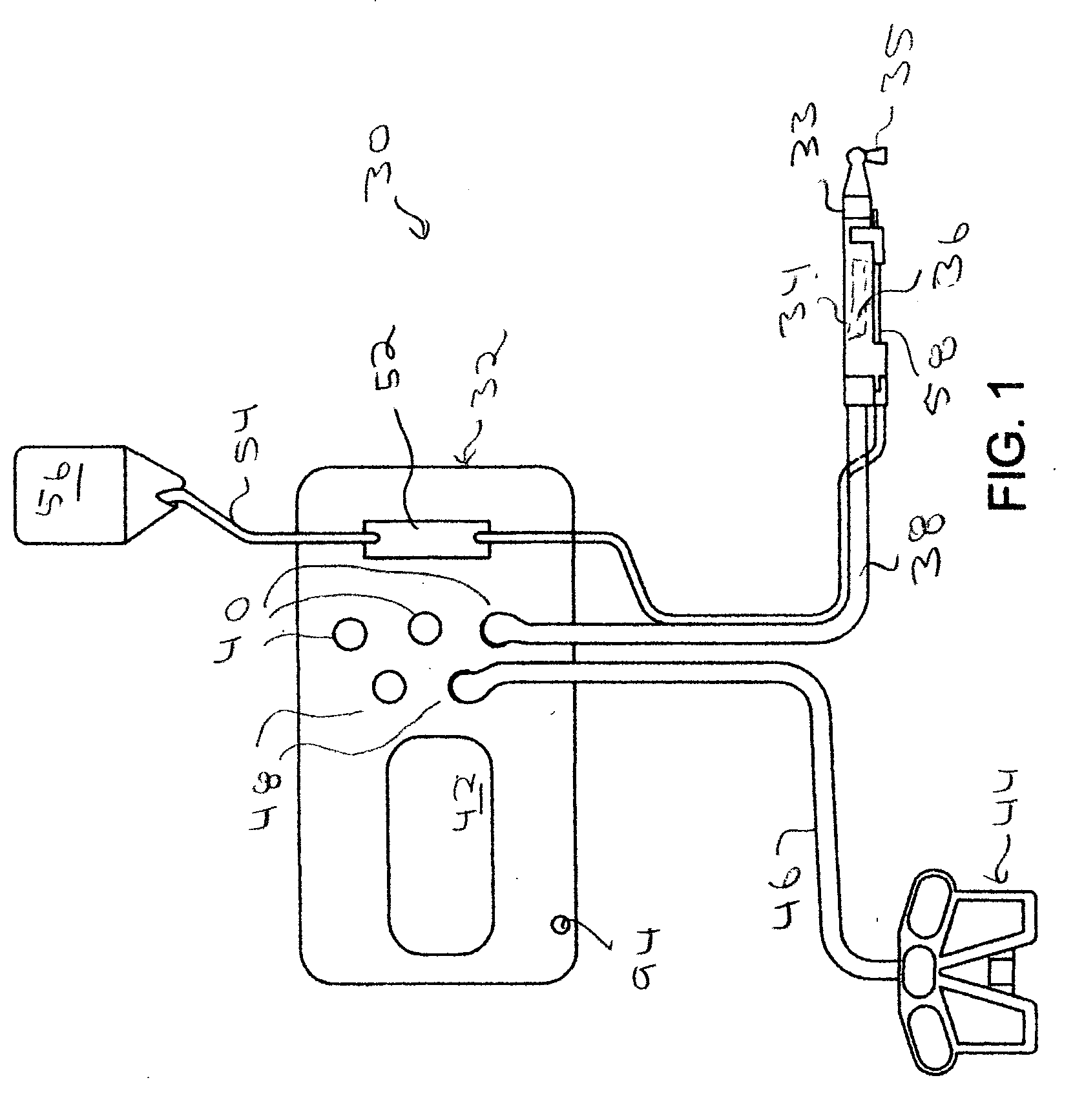
[0051]FIGS. 1, 2A and 2B illustrate the basic features of a surgical tool system 30 of this invention. System 30 includes a control console 32. The control console 32 is used to actuate one or more handpieces 34. In FIG. 1, a single handpiece 34, a saw, is illustrated. As seen by reference to FIG. 2B, it is possible to simultaneously connect three handpieces 34, to the control console 32. In the depicted version of the invention, internal to the handpiece 34 is a motor 36 (depicted as a phantom box) and a gear assembly (gear assembly not illustrated). Each handpiece 34 drives a cutting accessory 35 that is typically removably attached to the handpiece. In the illustrated handpiece 34 of FIG. 1, cutting accessory 35 is a saw blade that is removably attached to the distal end of the handpiece. (“Distal” means away from the surgeon / towards the patient. “Proximal” means towards the surgeon / away from the patient.) The illustrated handpiece 34 has a gear assembly designed to oscillate the...


PUM


Abstract

A surgical tool system including plural powered surgical handpieces. The handpieces are removably connected to a single control console. The control console has a power supply. A controller internal to the control console simultaneously supplies power to the plural handpieces. In the event the handpieces collectively draw more power than the power supply can provide, the control console temporarily stops the application of power to one of the handpieces.

Description

RELATIONSHIP TO EARLIER FILED APPLICATION [0001] This application claims priority under 35 U.S.C. Sec 119 from Provisional Application No. ______, having the same title as this application filed Sep. 29, 2004 under Express Mail Label No. ER 5757 09335 US.FIELD OF THE INVENTION [0002] This invention is related generally to a system for powering surgical tools. More particularly, this invention is related to a system for simultaneously powering surgical tools that have different power requirements. BACKGROUND OF THE INVENTION [0003] In modern surgery, powered surgical tools are some of the most important instruments medical personnel have available to them for performing certain surgical procedures. Many surgical tools take the form of some type of motorized handpiece to which a cutting accessory like a drill bit, a bur or a saw blade are attached. These tools are used to selectively remove small sections of hard or soft tissue or to separate sections of tissue. The ability to use pow...

Claims


Application Information

Patent Timeline
Patent Type & Authority Applications(United States)
IPC IPC(8): A61B17/00
CPCA61B17/1613A61B17/1622A61B17/1626A61B2017/00367A61B17/32002A61B2017/00017A61B2017/00199A61B17/1628A61B17/00A61B17/16A61B17/32A61B17/14A61B2017/00973
Inventor MALACKOWSKI, DONDOZEMAN, MICHAEL D.HOEKSTRA, PAUL M.WILDGEN, MICHAEL R.
Owner STRYKER CORP
Why Eureka
Try Eureka