Method of providing electric motor torque reserve in a hybrid electric vehicle

a hybrid electric vehicle and electric motor technology, applied in the direction of electric propulsion mounting, instruments, transportation and packaging, etc., can solve the problems of affecting the output torque that can be provided to the vehicle driveline, affecting the shift synchronization and overall shifting performance, and inability to control input speed, so as to improve the control robustness of the overall system, smooth output torque profile, and the effect of adding control robustness

Active Publication Date: 2005-11-17
GM GLOBAL TECH OPERATIONS LLC
View PDF10 Cites 202 Cited by
  • Summary
  • Abstract
  • Description
  • Claims
  • Application Information

AI Technical Summary

Benefits of technology

[0008] The method is preferably implemented as a computer control algorithm adapted for storage and execution in a controller, such as the system controller. The algorithm essentially provides an electric motor torque reserve to improve the control robustness of the overall system.
[0009] The algorithm allows for a smooth output torque profile to be present through a synchronous shift of the transmission by predicting when the shift will occur, and ensuring that enough electric motor torque reserve is present by that time to perform the shift fluidly (i.e., not requiring an abrupt change in output torque during the shift). The method is advantageous in that it adds control robustness and improved shift quality to the synchronous shift.
[0010] The algorithm also allows for the addition of more electric motor torque reserve reactively under cases where an input speed error exceeds a predetermined error limit. It observes the input speed error as it develops and makes the appropriate system level trade-offs (including the potential of dropping the magnitude of the peak allowable output torque) to give the electric motors the torque reserve necessary to attack the input speed error directly. This advantageously provides input speed control robustness.

Problems solved by technology

Such limitations include, for example, available engine torque, available electric machine torque and the available electrical energy storage system power.
In the case of the electric machine torque, the limitations that affect the output torque that can be provided to the vehicle driveline include the maximum and minimum torque output limits of the electric machine or machines.
For example, for synchronous shifts, the potential exists for a sudden change in output torque command at first synchronization because of a system output torque constraint change, such as a targeted input acceleration change; which may result in unacceptable input speed control if the system happens to be operating at or near one or more of the maximum or minimum motor torque limits.
Such limits can thus affect the shift synchronization and overall shifting performance.
This limitation may necessitate sudden and undesirable changes in transmission output torque or other transmission control parameters to affect the necessary input speed control.

Method used


Image

  • Method of providing electric motor torque reserve in a hybrid electric vehicle
  • Method of providing electric motor torque reserve in a hybrid electric vehicle
  • Method of providing electric motor torque reserve in a hybrid electric vehicle

Examples


Embodiment Construction

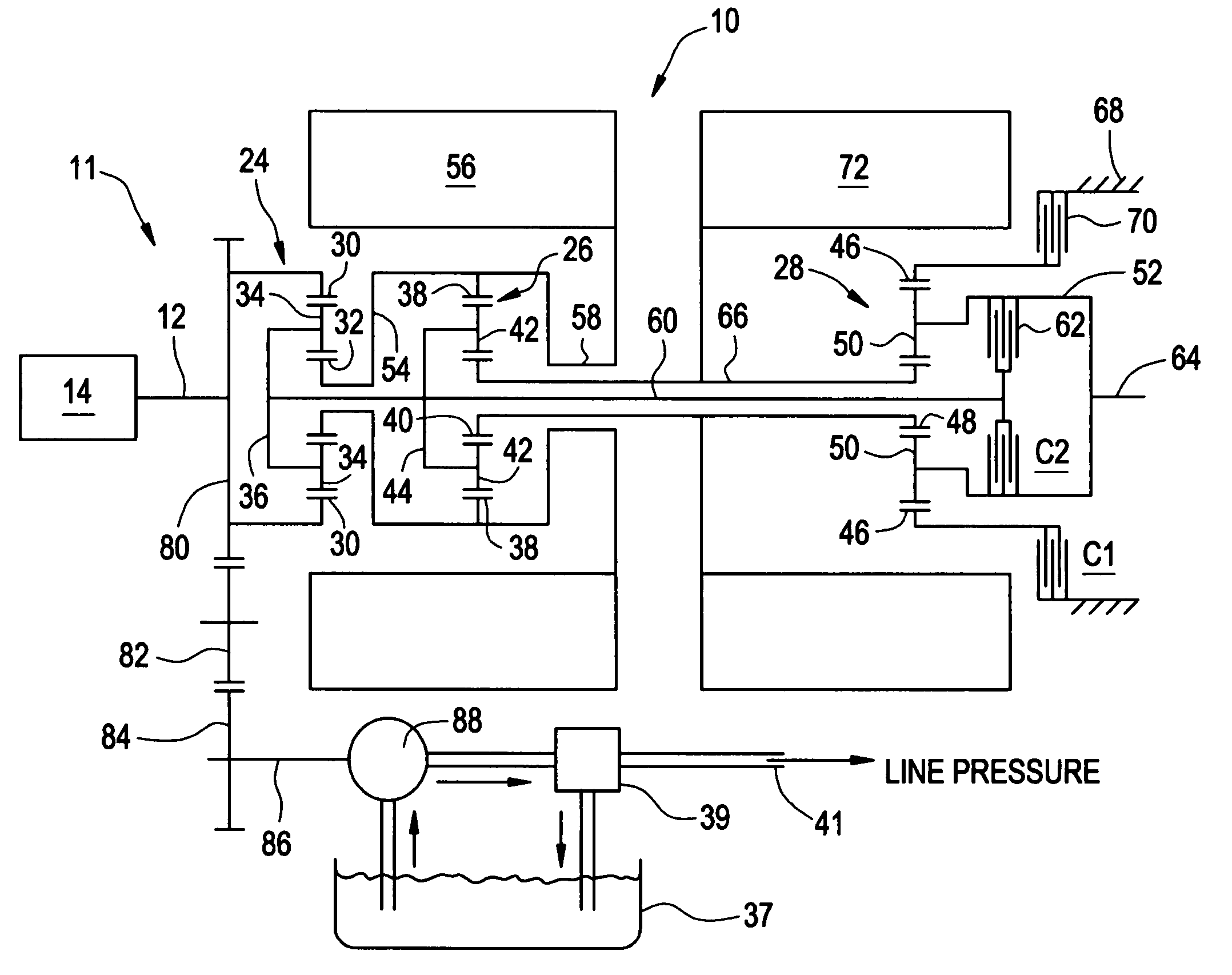
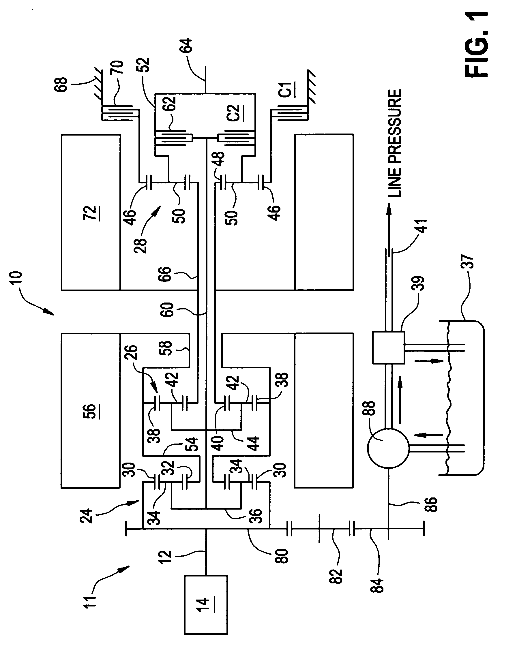
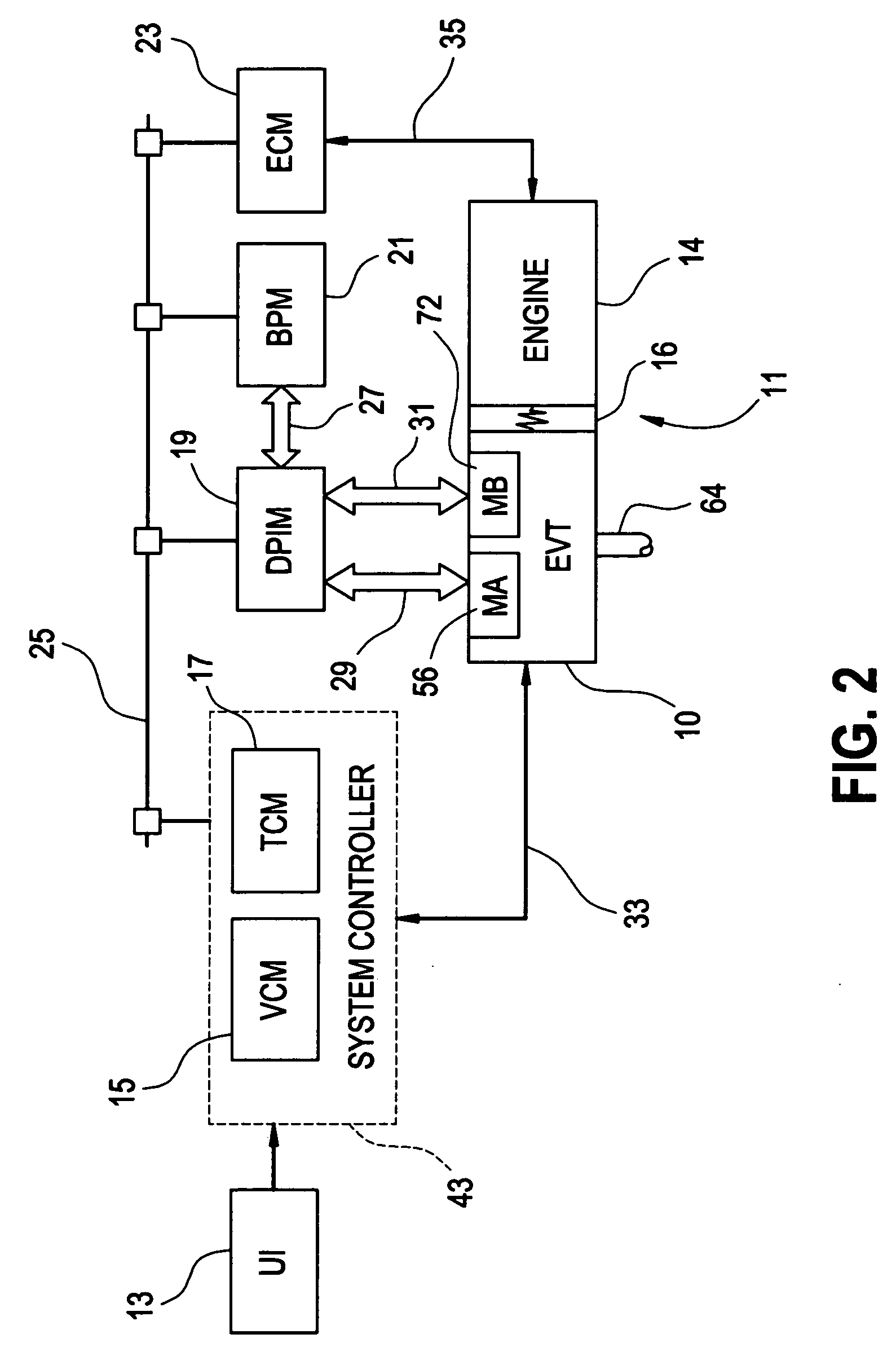
[0029] With reference first to FIGS. 1 and 2, a vehicular powertrain system is generally designated 11. Included in the powertrain 11 is one representative form of a multi-mode, compound-split, electrically variable transmission (EVT) particularly suited for implementing the controls of the present invention and designated generally by the numeral 10 in FIGS. 1 and 2. With particular reference, then, to those figures, the EVT 10 has an input member 12 that may be in the nature of a shaft which may be directly driven by an engine 14 or, as shown in FIG. 2, a transient torque damper 16 may be incorporated between the output member of the engine 14 and the input member of the EVT 10. The transient torque damper 16 may incorporate, or be employed in conjunction with, a torque transfer device (not shown) to permit selective engagement of the engine 14 with the EVT 10, but it must be understood that such a torque transfer device is not utilized to change, or control, the mode in which the...


PUM


Abstract

A method of operating a vehicle powertrain system comprising an electric motor and transmission where the electric motor is operably and selectively coupled to the transmission and adapted to provide an output torque contribution thereto, and the electric motor has a predetermined maximum motor output torque and a predetermined minimum motor output torque which are used to determine a range of permissible control points for at least one transmission control parameter. The method includes establishing a motor torque reserve by performing at least one of decreasing the predetermined maximum motor output torque to a maximum reserved motor output torque and increasing the minimum motor output torque to a minimum reserved motor output torque, wherein the maximum reserved motor output torque and the minimum reserved motor output torque are used in place of the predetermined maximum motor output torque and the predetermined minimum motor output torque, respectively, to determine the range of permissible control points for the at least one transmission control parameter. The motor torque reserve may include a static motor torque reserve, a dynamic motor torque reserve, or a combination of both static and dynamic torque reserves. The dynamic torque reserve may include a predictive dynamic reserve, a reactive dynamic reserve, or a combination of a predictive reserve and a reactive reserve or reserves.

Description

TECHNICAL FIELD [0001] The present invention is related to control of a vehicular powertrain system. More particularly, the invention is related to the control of the electric motors of a vehicle powertrain system which includes an electrically variable transmission (EVT). Most particularly, the present invention is a method of establishing an electric motor torque reserve for the electric motors of an EVT in order to improve the overall responsiveness of the EVT to actual or expected changes in transmission control parameters. BACKGROUND OF THE INVENTION [0002] Various hybrid powertrain architectures are known for managing the input and output torques of various prime-movers in hybrid vehicles, most commonly internal combustion engines and electric machines. Series hybrid architectures are generally characterized by an internal combustion engine driving an electric generator which in turn provides electrical power to an electric drivetrain and to a battery pack. The internal combus...

Claims


Application Information

Patent Timeline
Patent Type & Authority Applications(United States)
IPC IPC(8): B60K1/02B60L11/00B60W10/08B60W10/10B60W20/00
CPCB60K6/445Y10T477/23B60L2240/486B60W10/08B60W10/105B60W20/00B60W2510/0241B60W2510/025B60W2510/102B60W2710/083F16H2061/6603Y02T10/84Y02T10/642Y02T10/6239B60L2240/423Y02T10/62Y02T10/64B60W20/30
Inventor HEAP, ANTHONY H.HSIEH, TUNG-MINGHUBBARD, GREGORY A.
Owner GM GLOBAL TECH OPERATIONS LLC
Why Eureka
Try Eureka