Radio network node and a wireless device, and methods therein

a wireless device and network node technology, applied in the field of wireless devices, can solve the problems of high risk of unsuccessful decoding of ack/nack reports, unacceptable mobile network operators, and the number of resources used for transmission of ack/nack reports and/or assignment messages, so as to improve the robustness of control signaling, reduce the number of so-called silent fixed allocations, and improve the likelihood

Active Publication Date: 2018-11-15
TELEFON AB LM ERICSSON (PUBL)
View PDF10 Cites 1 Cited by
  • Summary
  • Abstract
  • Description
  • Claims
  • Application Information

AI Technical Summary

Benefits of technology

[0034]An advantage with embodiments herein is that they improve the robustness of control signaling in the communications network, to improve the likelihood of e.g. assignment messages to be decoded by a receiver, e.g. by a receiving node, e.g. the wireless device. As a consequence the number of so called silent fixed allocations may be reduced.
[0035]Herein, the term “fixed allocation” refers to an assignment of a certain number of radio resources to a certain transmitter, e.g. a certain transmitting node, e.g. the RNN. If e.g. a wireless device is able to decode a received assignment message sent in the DL containing a for the wireless device Fixed Uplink Allocation (FUA), the wireless device will as a consequence utilize those allocated UL radio resources specified by the FUA for transmission. However, if the wireless device fails to decode the assignment message, i.e. the FUA, due to an insufficiently robust radio link it will as a result not transmit, i.e. remain silent, during the fixed allocation. Those resources would thus not be utilized. Further, embodiments herein will also reduce the number resources used for transmission of ACK / NACK-reports and / or assignment messages that would have a high risk of being unsuccessfully decoded. This will reduce the interference caused by transmission of ACK / NACK-reports and / or assignment messages and help to conserve battery in the wireless device.
[0036]Another advantage of embodiments disclosed herein is that the number of unsuccessful connections, e.g. uplink Temporary Block Flows (TBFs), will be decreased since fewer connections, e.g. uplink TBFs, will be lost due to unsuccessful reception of the ACK / NACK and / or assignment messages. Since such an unsuccessful connection may lead to devices needing to restart packet connection establishment procedures via the common control channel, the load on the common control channel would thus be decreased. The power consumption in the device would then also be decreased.
[0037]Yet another advantage of embodiments disclosed herein is that they will increase the probability of successful reception of paging messages and / or control messages sent on the common control channel.

Problems solved by technology

However, this may very quickly result in unreasonable investment effort and will not be acceptable to Mobile Network Operators (MNOs).
However, if the wireless device fails to decode the assignment message, i.e. the FUA, due to an insufficiently robust radio link it will as a result not transmit, i.e. remain silent, during the fixed allocation.
Further, embodiments herein will also reduce the number resources used for transmission of ACK / NACK-reports and / or assignment messages that would have a high risk of being unsuccessfully decoded.
However, when operating in extended coverage the estimation of the coverage class required for the wireless device to communicate with the network, e.g. the RNN, may be difficult to assess for the wireless device, since the wireless device is operating at a low signal level, possibly even weaker than the thermal noise in the wireless device.
However, due to a requirement on long battery lifetime it may not be possible for the wireless device to frequently measure its surrounding radio environment.
These effects give rise to the wireless device possibly being in the sub-optimal coverage class when communicating with the network, e.g. the RNN, possibly resulting in a high block error rate on the channel used for communication, and an inefficient, or in worst case lost, communication link.
When considering the case of EC-EGPRS, only a small portion of the wireless devices are expected to be in extended coverage, and hence dimensioning all control signaling for the worst coverage range, e.g. the maximum coupling loss for the extended coverage operation, is a significant waste of resources.
There is a risk that the second assignment message also will be lost, which will lead to a second silent FUA.
This risk is obviously higher if the first assignment message could not be successfully received due to that the level of coverage extension used for the transmission was not sufficient, and the same level is used for the second message.
Hence, losing assignment messages may result in a significant number of silent FUAs and a lot of resources for transmission of data units being unused.
It may also lead to a lot of assignment messages and therefore a lot of radio resources for transmission of control messages being used.The uplink data transmission transfer may be abnormally terminated by both the network and the wireless device when a silent FUA occurs.
Since the resources available to set up new TBFs are generally scarce the relative number of resources required for the transfer will be high and the device will experience additional battery drain.
If the network does not receive an ACK / NACK report that negatively acknowledges blocks, the network will not know what downlink data blocks need to be retransmitted.
In case that e.g. a worsened radio condition in the uplink direction remains, the wireless device may be successfully polled on the downlink but several corresponding ACK / NACK reports may be lost, which then eventually may lead to an abnormal release of the downlink (DL) TBF.
The same issue appears when a worsened radio condition is experienced in the downlink direction during the downlink data transmission.
This may thus lead to that the wireless device does not successfully receive any data blocks, even though transmitted by the network, e.g. the network and / or the RNN.
If the worsened radio condition remains, the wireless device would then not be able to receive any downlink data block being transmitted by the network, e.g. the network and / or the RNN.
In either case, it may eventually lead to an abnormal release of the DL TBF and a new DL TBF would then need to be set up, using additional control signaling and consuming additional battery, in order to finish the transfer.
The more extreme coverage may be due to higher path loss, but may also be associated with higher interference levels etc.
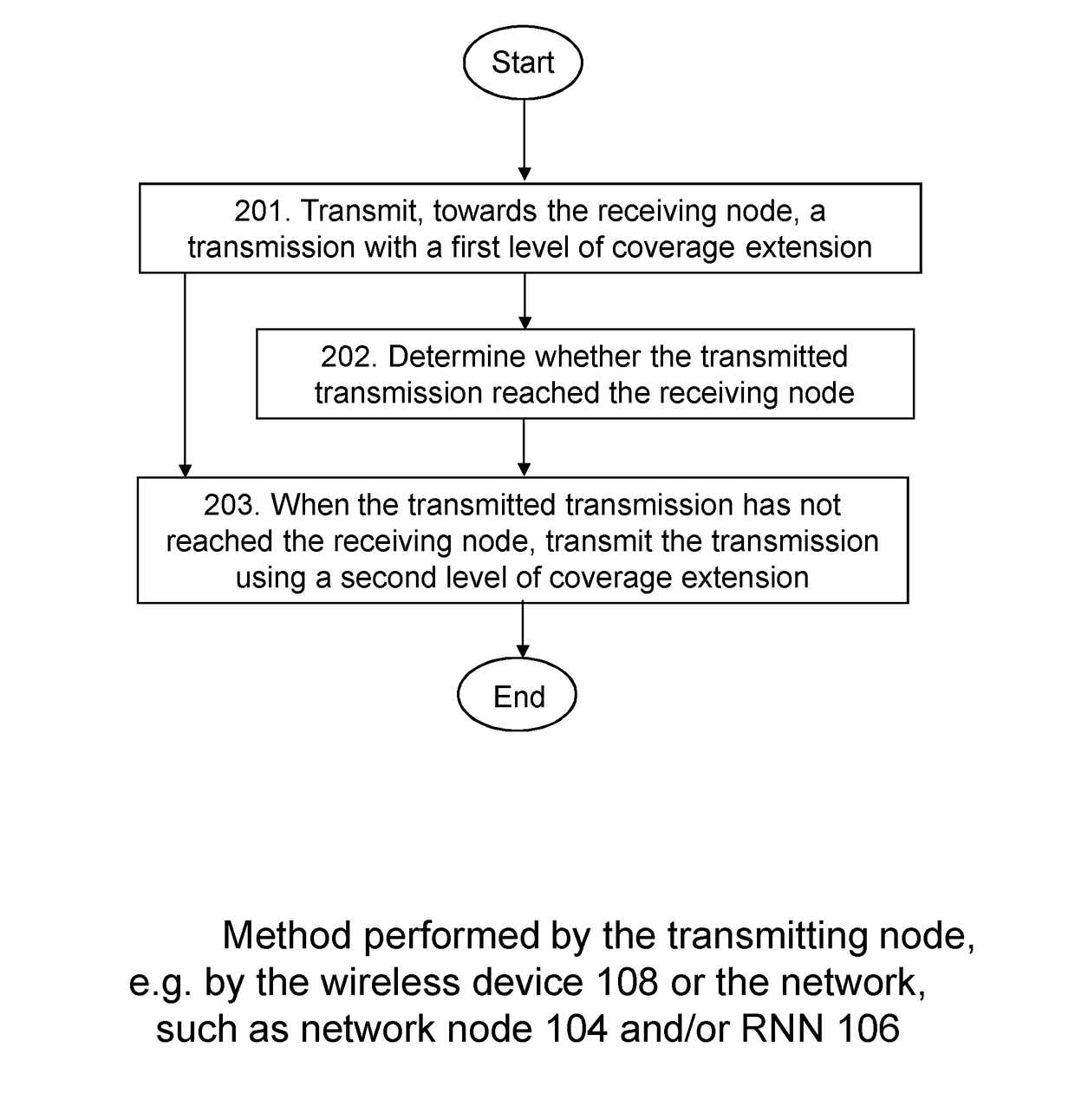
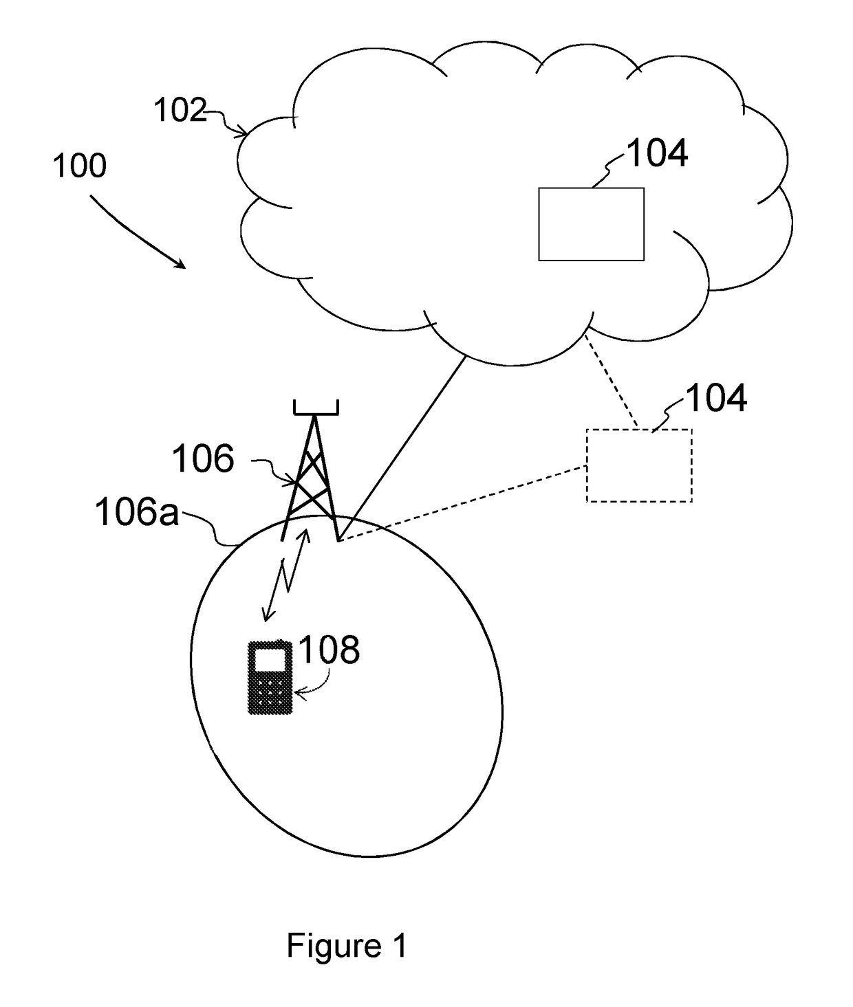
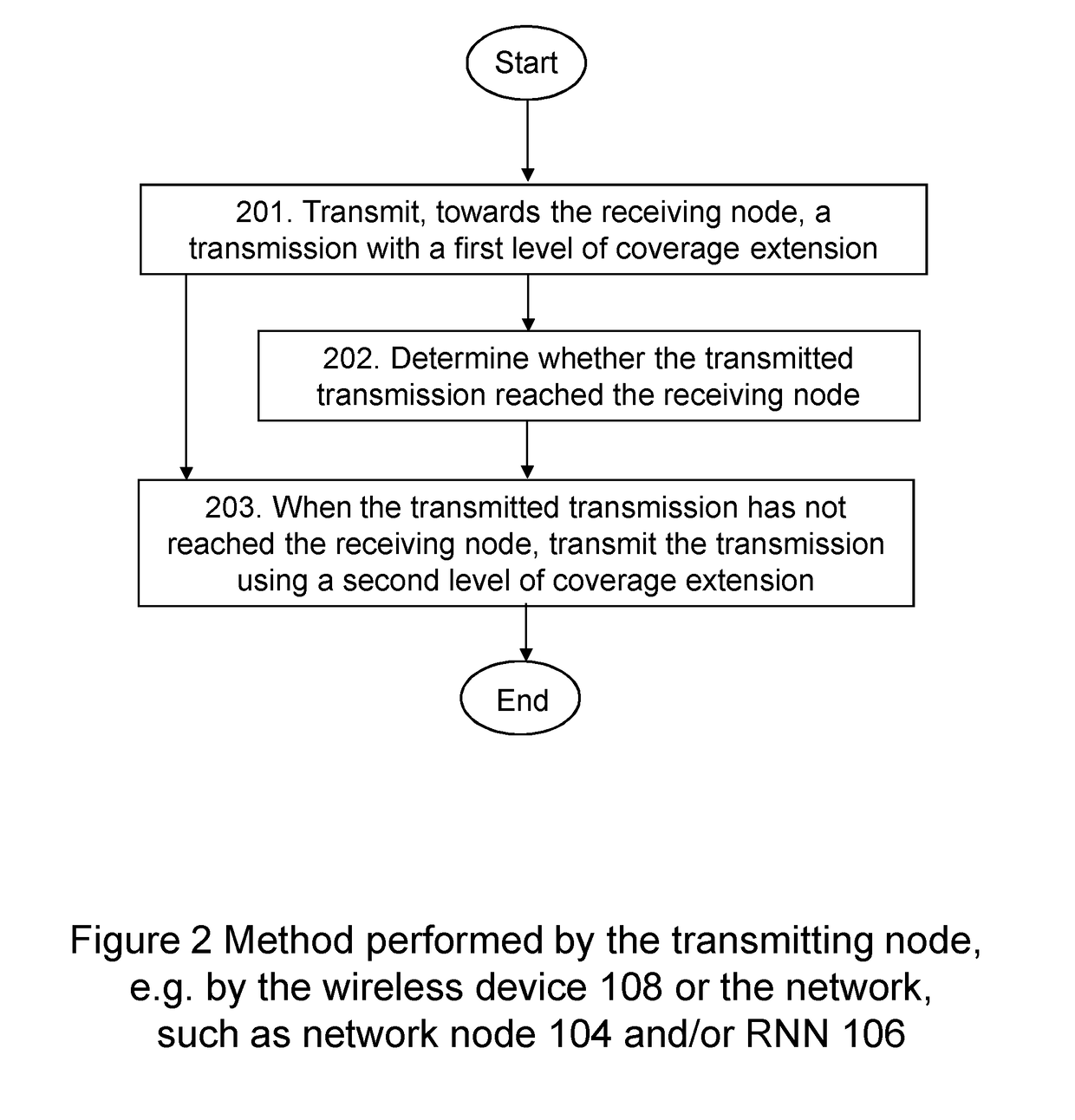
However, the transmission may or may not reach the wireless device 108.
Further, an unsuccessful reception may cause the receiving node to listen to a later (re)transmission at a later point in time, with a higher level of coverage extension, e.g. with a higher CC.

Method used


Image

  • Radio network node and a wireless device, and methods therein
  • Radio network node and a wireless device, and methods therein
  • Radio network node and a wireless device, and methods therein

Examples


first embodiments

Some First Embodiments

General Application

[0211]In some first embodiments, the network, e.g. the network node 104 and / or the RNN 106, controls what CC to use when transmitting to the wireless device 108. The wireless device 108 in its turn is mandated to monitor the set of CCs possibly used by the network. This has the advantage that the network need not signal to the wireless device 108 what number of repetitions to look for, but the disadvantage that the wireless device will unnecessarily monitor the DL channel more often in the case that no data is transmitted to the device.

[0212]Exemplifying procedures for the network, e.g. the network node 104 and / or the RNN 106, and the wireless device 108 are schematically illustrated in FIGS. 6A and 6B. It may be noted that the network, e.g. the network node 104 and / or the RNN 106, and wireless device 108 behaviour may be specified so that for example only one increase of CC is applied. It may further be noted that in case a maximum CC is spe...

second embodiments

Some Second Embodiments

General Application

[0215]In some second embodiments, the network, e.g. the network node 104 and / or the RNN 106, and the wireless device 108 initially make use of the same scheme, e.g. the same Coverage Class, in each direction, according to e.g. a previous communication or a pre-determined value. For a data transfer it may e.g. be initially communicated between the wireless device 108 and the network at the assignment of resources for the transfer. The Coverage Class used may however be different in the uplink and downlink directions.

[0216]The network, e.g. the RNN 106, and wireless device 108 are then aligned on a specific point in time where the Coverage Class (CC) in the downlink (DL), uplink (UL), or both directions, is / are to be increased. The specific point in time may be communicated between the wireless device 108 and the network, e.g. the RNN 106. For example, this may be done at assignment of resources for a transfer, may be sent as broadcast informa...

third embodiments

Some Third Embodiments

[0243]Some third embodiments correspond to some second embodiments, with the difference that the change to a more robust scheme, e.g. to use a higher CC, is triggered by a specific event instead of a specific point in time. Such an event may be, as an example, that the wireless device 108 at certain points in time estimates its DL coverage, e.g. as Coverage Class, during an ongoing transfer. If the estimation indicates that the DL coverage has become worse than what was initially communicated between the wireless device 108 and the network, e.g. the network node 104 and / or the RNN 106, for the transfer, the wireless device 108 starts monitoring the DL using a more robust scheme. The event triggering the network to start using a more robust scheme may then e.g. be that the wireless device 108 informs the network about the worsened DL coverage. As an alternative, the fact that the network does not receive any, or too little amount of, data / response from the wirel...


PUM


Abstract

A Radio Network Node (RNN) and a method therein for providing improved robustness of a radio link between the RNN and a wireless device. The RNN and the wireless device operate in a communications network. The RNN transmits, towards the wireless device, a transmission with a first transmission mode associated with a first level of coverage extension. When a first period of time has elapsed, the RNN transmits, towards the wireless device, the transmission using a second transmission mode associated with a second level of coverage extension. The second level of coverage extension is higher than the first level of coverage extension.

Description

TECHNICAL FIELD[0001]Embodiments herein relate to a Radio Network Node (RNN), a wireless device, and to methods therein. Especially, embodiments herein relate to providing improved robustness of a radio link between the RNN and the wireless device operating in a communications network.BACKGROUND[0002]In the field of wireless communication, communication devices such as terminals or wireless devices are also known as e.g. User Equipments (UE), stations (STAs), mobile terminals, wireless terminals and / or Mobile Stations (MS). Such terminals are enabled to communicate wirelessly in a wireless communication system, such as a Wireless Local Area Network (WLAN), or a cellular communications network , sometimes also referred to as a cellular radio system or cellular networks. The communication may be performed e.g. between two terminals, between a terminal and a regular telephone, between a terminal and an Access Point (AP), and / or between a terminal and a server via a Access Network (AN) ...

Claims


Application Information

Patent Timeline
Patent Type & Authority Applications(United States)
IPC IPC(8): H04W24/02H04L1/08
CPCH04W24/02H04L1/08H04L1/0001H04L1/1671H04L1/1685H04L1/1896
Inventor SUNDBERG, MARTENHANDEL, ULFBERGQVIST, JENSSAGEBRAND, BIRGITTALIBERG, OLOFDIACHINA, JOHN WALTERERIKSSON LOWENMARK, STEFANSCHLIWA-BERTLING, PAUL
Owner TELEFON AB LM ERICSSON (PUBL)
Why Eureka
Try Eureka