Electrical wheel brake actuator with improved end position recognition

a technology of end position recognition and actuator, which is applied in the direction of braking systems, mechanical equipment, transportation and packaging, etc., can solve the problems of difficult ambient conditions, unbraked travel of the actuator into the release end stop position, and customer perception of uncomfortable unbraked travel of the actuator, so as to improve the end position recognition and simplify production.

Pending Publication Date: 2021-12-09
CONTINENTAL TEVES AG & CO OHG
View PDF0 Cites 1 Cited by
  • Summary
  • Abstract
  • Description
  • Claims
  • Application Information

AI Technical Summary

Benefits of technology

[0004]An aspect of the present invention allows an improved end position recogn

Problems solved by technology

However, the rotor and drive-gear train of these wheel brake actuators are subject to friction and inertia.
The system must also function reliably under

Method used


Image

  • Electrical wheel brake actuator with improved end position recognition
  • Electrical wheel brake actuator with improved end position recognition
  • Electrical wheel brake actuator with improved end position recognition

Examples


Embodiment Construction

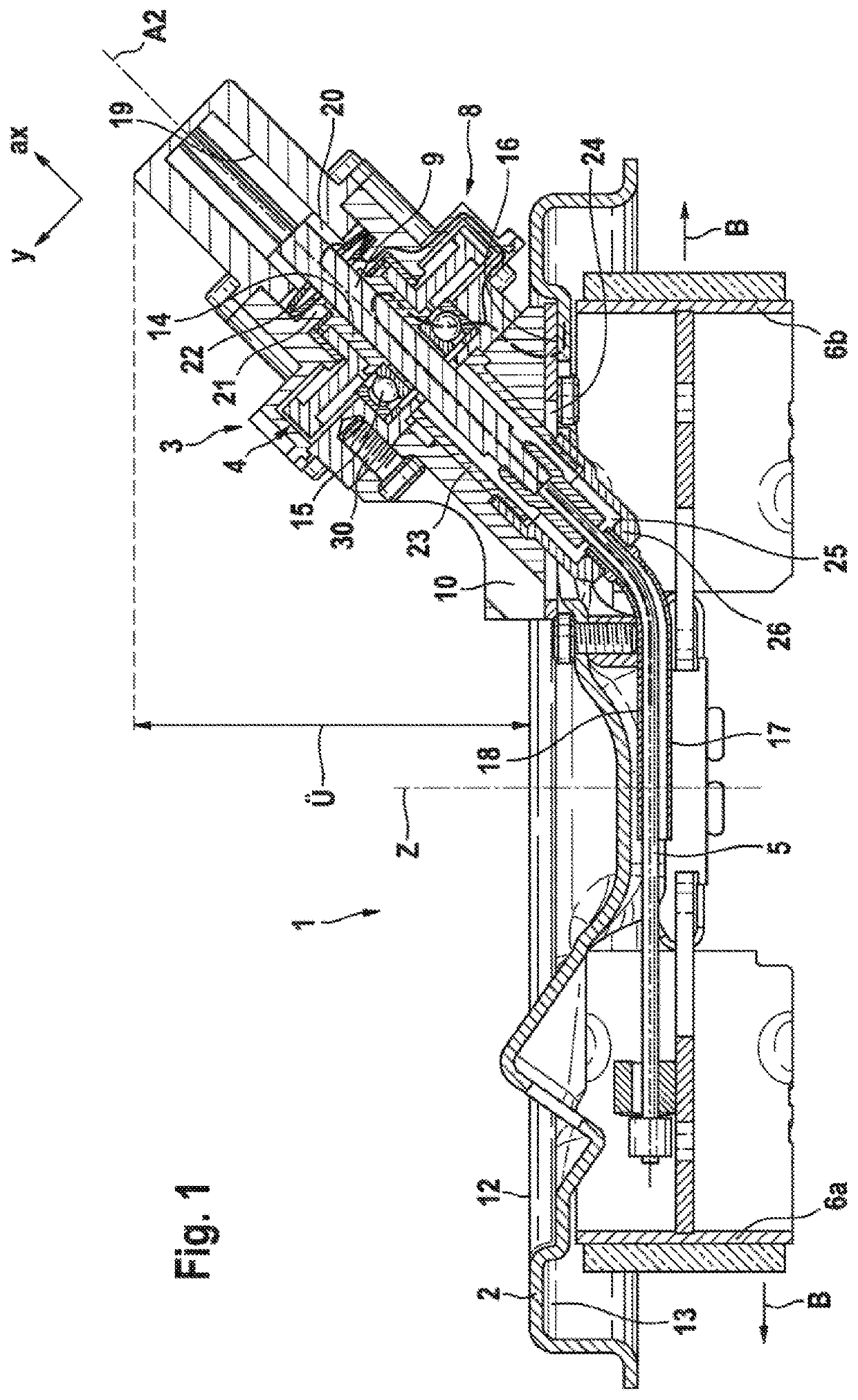
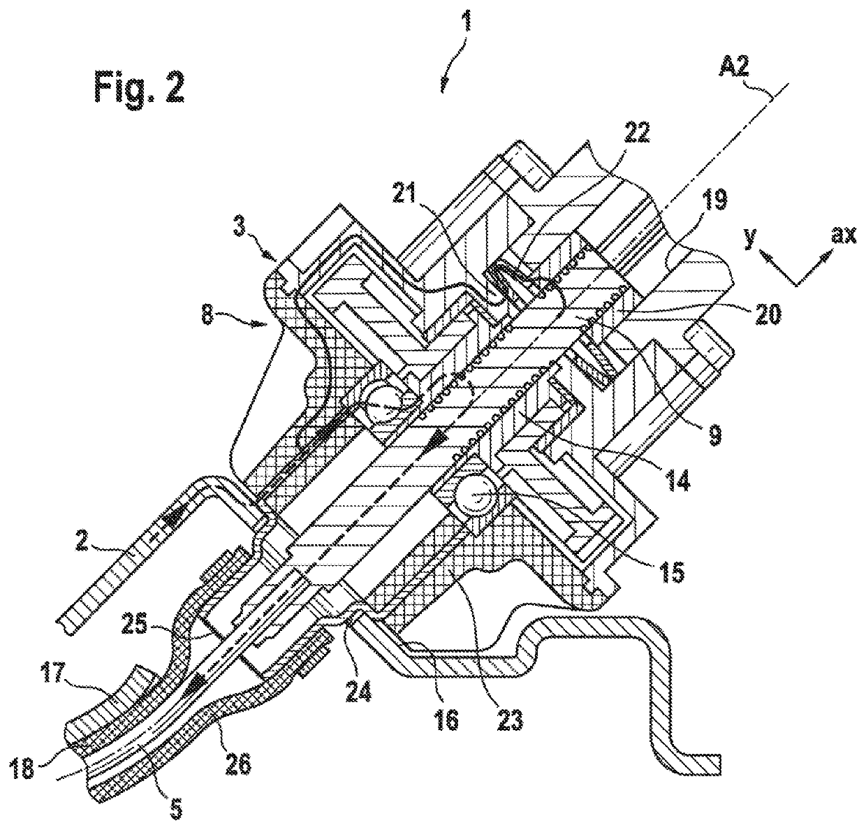
[0014]A known drum brake module 1, actuatable by electric motor, for arrangement on axle components of a motor vehicle comprises, as per FIG. 1, a brake holder 2 on which brake means 6a,b are mounted in cooperation with a brake rotor (not shown). On an opposite side of the brake holder 2, there is fastened a cable-pull actuator 3 which is driven by electric motor and which, via a gearing 4 and a downstream cable-pull 5, engages on one or more brake means 6a,b such that said brake means 6a,b can perform an actuation movement B in the direction of the brake rotor, in order to execute a service and / or parking brake function. A support device 11 may be provided between the brake means 6a,b.

[0015]The gearing 4 comprises a gear housing 8 which receives or at least supports the motor 7. The motor 7 consumes direct-current voltage, is mechanically or electronically commutated, and is of an inexpensively available standard type.

[0016]FIG. 1, in any case indirectly, illustrates that an axis ...


PUM


Abstract

An electrical wheel brake actuator for motor vehicles, designed to move a brake pad in the direction of a brake rotor and having an electric motor-gear assembly with a rotation-translation converter assembly that includes a nut-spindle arrangement, and an elastic element which is associated with a release end stop of the spindle arrangement in order, together with a control unit, to allow the electric motor to be automatically electrically switched off. The elastic element includes at least two disc springs which are able to form an expanded segmented force-travel spring curve formed from multiple force-travel spring curve portions.

Description

CROSS REFERENCE TO RELATED APPLICATIONS[0001]This application is the U.S. National Phase Application of PCT International Application No. PCT / EP2019 / 075814, filed Sep. 25, 2019, which claims priority to German Patent Application No. 10 2018 216 509.2, filed Sep. 26, 2018, the contents of such applications being incorporated by reference herein.FIELD OF THE INVENTION[0002]The present invention concerns an electric cable-pull actuator 3 as may be used in particular for a drum brake module 1 which is actuated by an electric motor. This may in particular include an electromechanical cable-pull brake actuator 3 with gear housing 8, the gear housing sump of which with a cable-pull outlet on the wheel brake side is arranged on an outside 12 of a brake holder 2 or brake carrier, and comprises a rotation-translation converter which as a result of a rotational drive motion generates a translational actuating motion (B) of brake means 6a,b that are arranged on an inside 13 of the brake holder ...

Claims


Application Information

Patent Timeline
IPC IPC(8): B60T13/74F16D65/22B60T1/06F16D51/22
CPCB60T13/741F16D65/22F16D2066/003F16D51/22B60T13/746B60T1/067F16D2125/40F16D2125/62F16D2121/24F16D2125/48F16D2125/50F16D2125/52F16D2066/006F16D2127/02
Inventor WINKLER, THOMASBALZ, JÜRGEN
Owner CONTINENTAL TEVES AG & CO OHG
Why Eureka
Try Eureka