
Distributed architecture for digital program insertion in video streams delivered over packet networks

a technology of video stream and packet network, applied in the field of digital broadcast video streaming technology, can solve the problems of limited number of video output streams that can be delivered to different targeted groups, limited amount of targeting, and bandwidth consumption placing an upper limit on the amount of targeting that can be performed

Inactive Publication Date: 2006-04-06
CISCO TECH INC
View PDF74 Cites 199 Cited by
  • Summary
  • Abstract
  • Description
  • Claims
  • Application Information

AI Technical Summary

Problems solved by technology

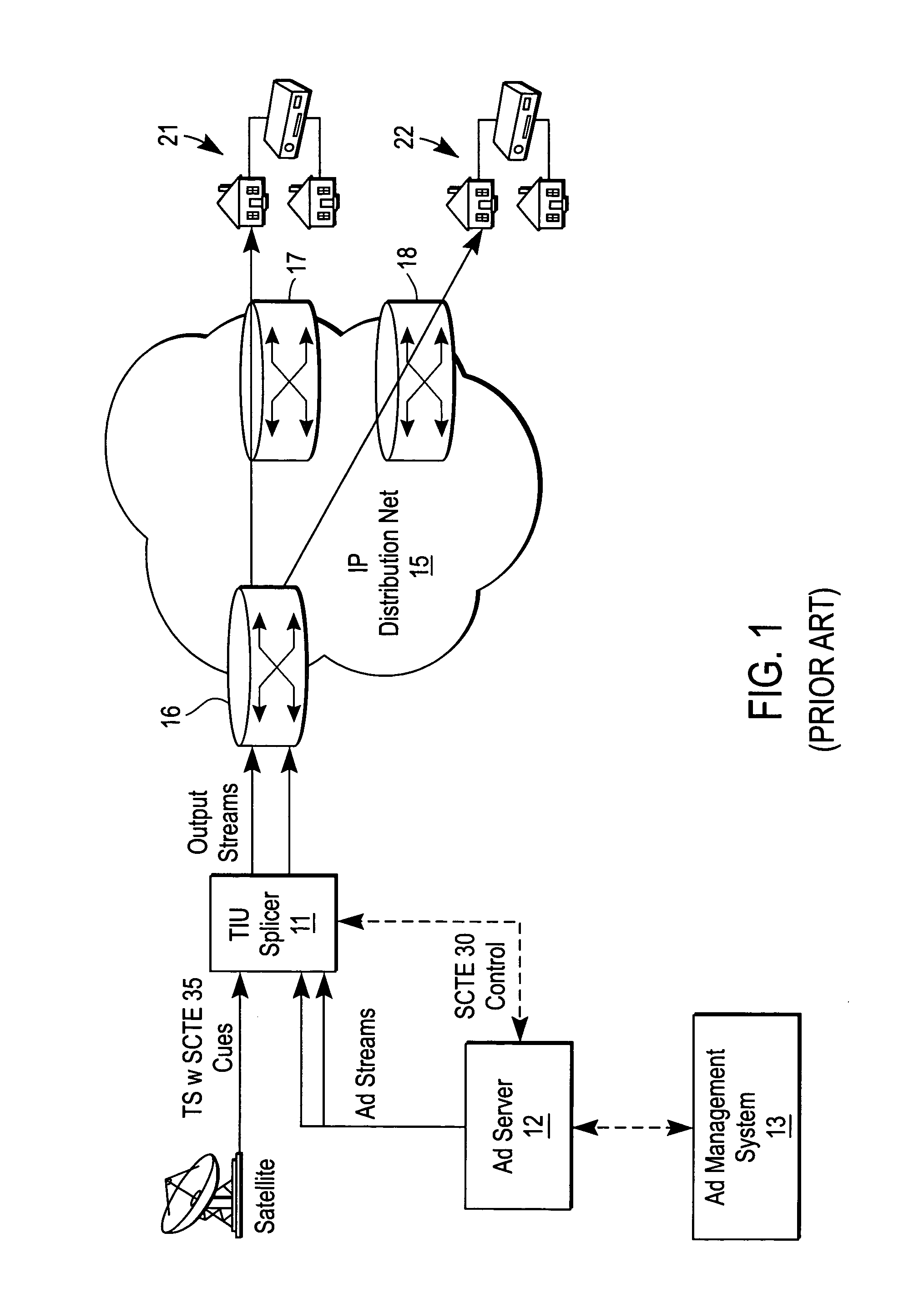
One of the drawbacks of the conventional system shown in FIG. 1 is that the number of video output streams that can be delivered to different targeted groups is limited by the available bandwidth of distribution network 15.
Hence, only a limited amount of targeting can be achieved.
In other words, although the centralized architecture shown in FIG. 1 permits some targeting of ads to multiple groups, the problem is that bandwidth consumption places an upper limit on the amount of targeting that can be performed.
However, the problem with this approach is that it adds significant cost to the overall system, since expensive splicers are required at multiple edge locations.
Yet another problem with existing DPI systems is that it is often difficult to insure a seamless, high-quality transition into and out of the network stream.
That is, expensive low-level processing is required to condition the digital video stream in order to guarantee seamless splicing of ads.
Although this technique is simple and relatively inexpensive, it only works well in certain limited cases, such as well-conditioned streams in which there are no open GOPS, i.e., a GOP having a B-frame that can only be decoded by reference to the I-frame of a next GOP, or when the pictures are perfectly aligned with the packet boundary.
Thus, there remains an unsatisfied need for a new DPI architecture that overcomes the aforementioned problems in the prior art.

Method used


Image

  • Distributed architecture for digital program insertion in video streams delivered over packet networks
  • Distributed architecture for digital program insertion in video streams delivered over packet networks
  • Distributed architecture for digital program insertion in video streams delivered over packet networks

Examples


Embodiment Construction

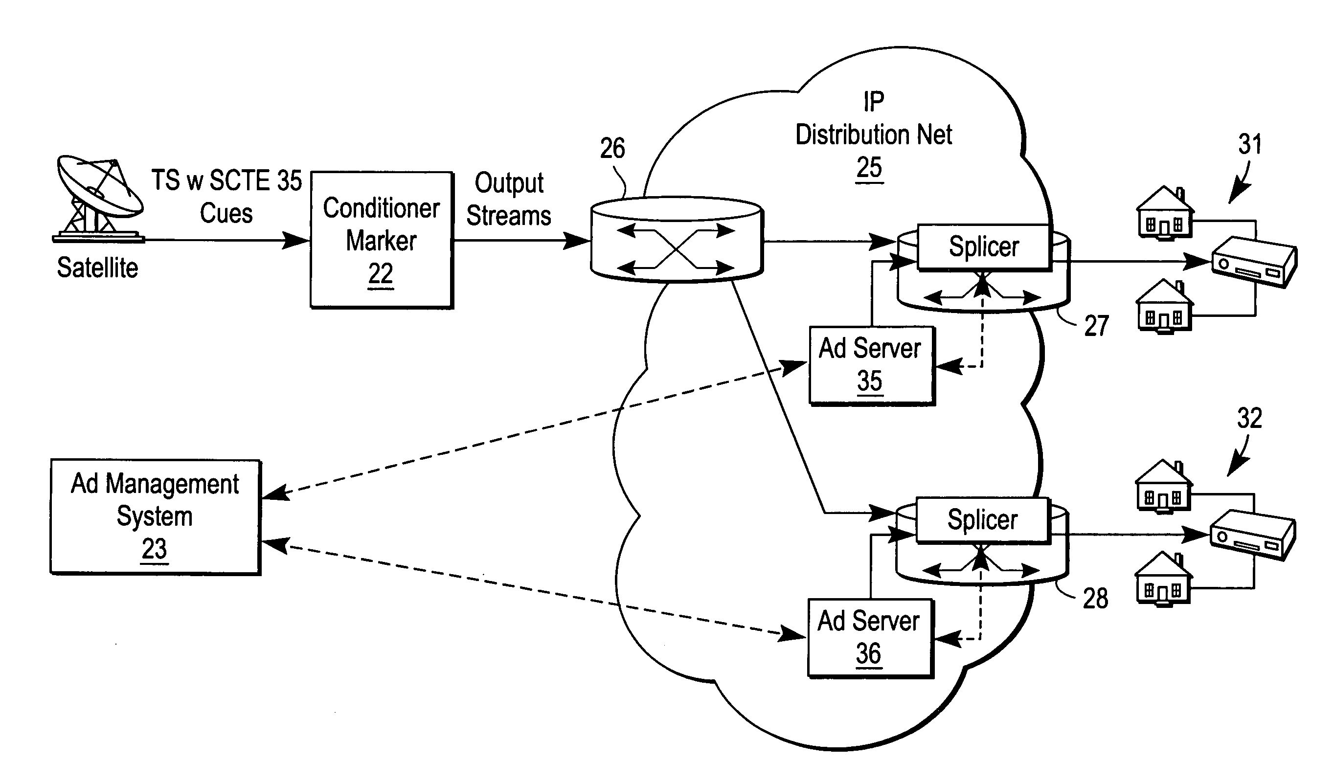
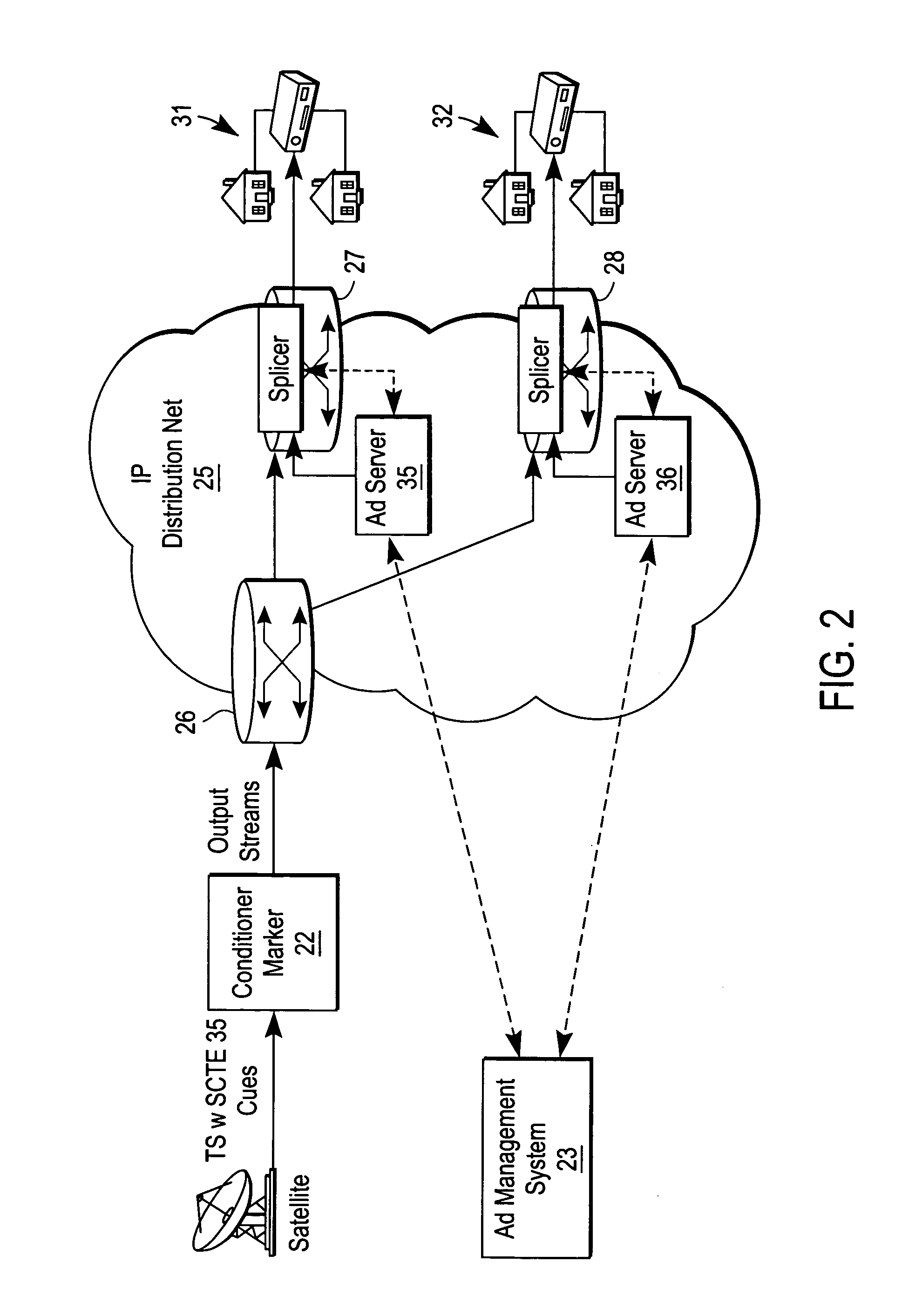
[0016] A system for fine grain or personalized targeted ad-insertion in a digital video transport stream is described. In the following description, numerous specific details are set forth, such as device types, protocols, configurations, etc., in order to provide a thorough understanding of the present invention. However, persons having ordinary skill in the networking arts will appreciate that these specific details may not be needed to practice the present invention.

[0017] In the context of the present application, it should be understood that a computer network is a geographically distributed collection of interconnected subnetworks for transporting data between nodes, such as intermediate nodes and end nodes. A local area network (LAN) is an example of such a subnetwork; a plurality of LANs may be further interconnected by an intermediate network node, such as a router or switch, to extend the effective “size” of the computer network and increase the number of communicating no...


PUM


Abstract

A system and method for digital ad insertion includes a unit to mark a video bitstream with Internet protocol (IP) splice points based on cue tone signals embedded within the video bitstream. The unit outputs a single transport stream (TS) that is sent across a packet-based network. A splicing device with an associated ad server is operable to receive the TS and detect the IP splice points. The splicing device signaling the ad server to retrieve one or more ads for insertion into the TS at one of the IP splice points. It is emphasized that this abstract is provided to comply with the rules requiring an abstract that will allow a searcher or other reader to quickly ascertain the subject matter of the technical disclosure. It is submitted with the understanding that it will not be used to interpret or limit the scope or meaning of the claims.

Description

FIELD OF THE INVENTION [0001] The present invention relates generally to the field of digital broadcast video streaming technology; more particularly, to personalized or targeted ad insertion into a digital broadcast stream. BACKGROUND OF THE INVENTION [0002] The cable and satellite television industry has experienced explosive growth in recent years. Not surprisingly, the sale and insertion of local and regional advertisements have become a huge source of revenue for cable television system operators that deliver programs to their subscriber customers. In the past, analog video ads were commonly inserted into analog satellite video feeds by the local cable operators. Most often, analog ads were stored on tape and switched into the network feed by analog video switches, with the switching process being triggered by a cue tone sequence on the associated audio feeds delivered together with the video feed and received by a satellite receiver. As more cable systems have been converted t...

Claims


Application Information

Patent Timeline
IPC IPC(8): H04N7/173
CPCG06Q30/02H04N7/165H04N21/23424H04N21/2668H04N21/64322H04N21/812
Inventor JAGADEESAN, RAMANATHAN T.MAY, WILLIAM B. JR.WU, FANG
Owner CISCO TECH INC
Learn More