
Debris retention perforating apparatus and method for use of same

a perforating apparatus and debris technology, applied in the direction of wellbore/well accessories, nuclear explosives, nuclear engineering, etc., can solve the problems of obstructing the passage of tools through the casing, fragments often falling out or being blown out, and fragments becoming debris

Inactive Publication Date: 2006-04-13
HALLIBURTON ENERGY SERVICES INC
View PDF24 Cites 39 Cited by
  • Summary
  • Abstract
  • Description
  • Claims
  • Application Information

AI Technical Summary

Benefits of technology

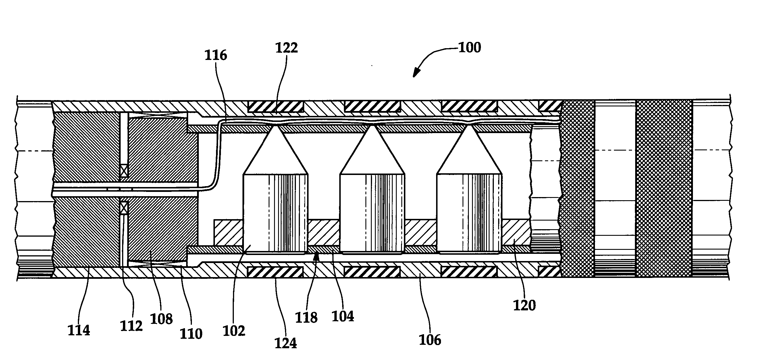
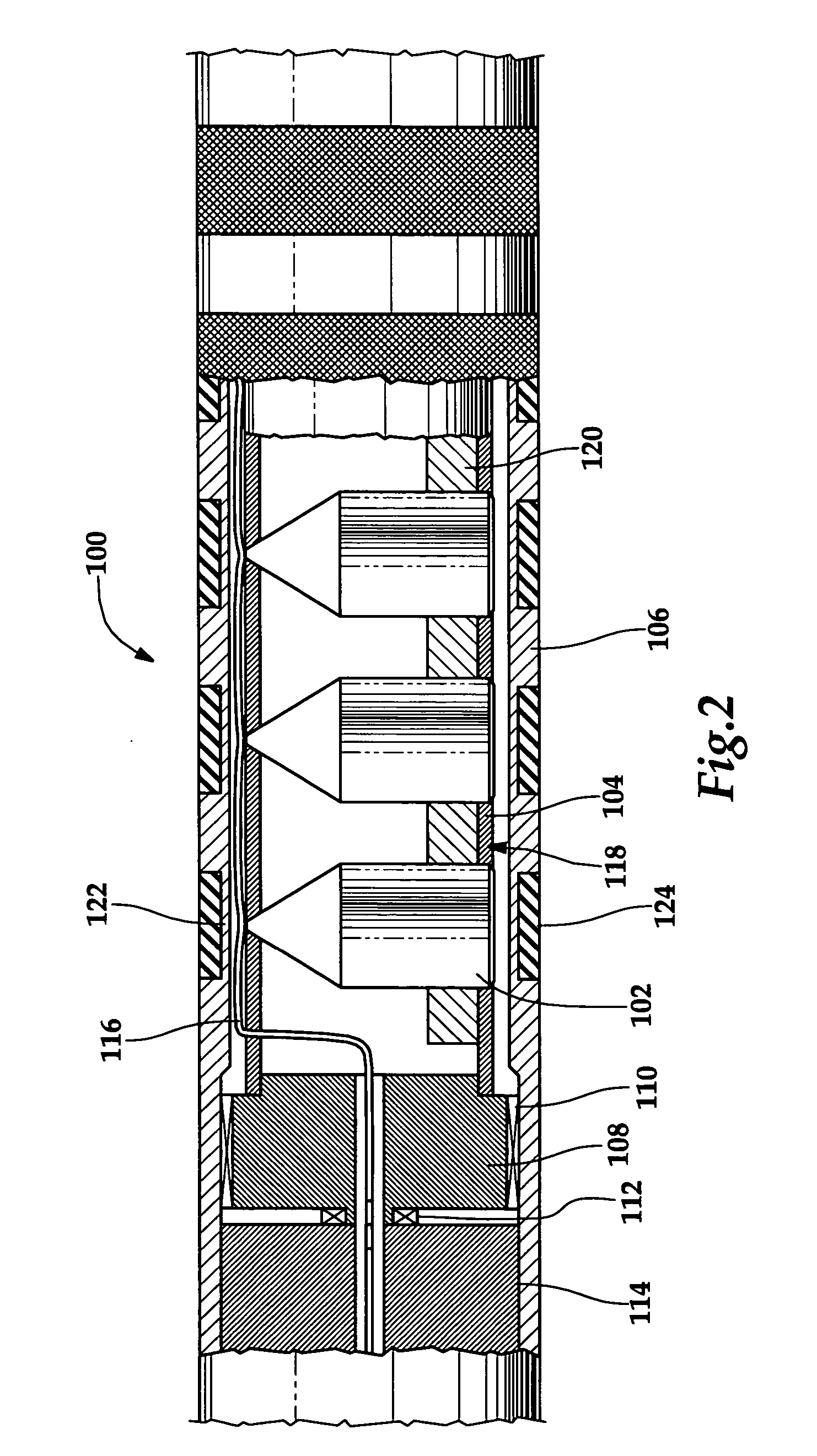
[0013] In yet another aspect, the present invention is directed to a method for retaining debris in a perforating apparatus used to perforate a subterranean well that includes running the perforating apparatus downhole, detonating a shaped charge contained within a carrier of the perforating apparatus and discharging a jet formed from the shaped charge through a discharge location of the carrier such that an opening is created through first and second material layers of the discharge location, wherein the opening in the first material layer is larger than the opening in the second material layer, thereby retaining debris in the perforating apparatus with the second material layer.

Problems solved by technology

These fragments often fall out or are blown out of the holes created in the carrier.
As such, these fragments become debris that is left behind in the wellbore.
It has been found that this debris can obstruct the passage of tools through the casing during subsequent operations.
This is particularly problematic in the long production zones that are perforated in horizontal wells as the debris simply piles up on the lower side of such wells.

Method used


Image

  • Debris retention perforating apparatus and method for use of same
  • Debris retention perforating apparatus and method for use of same
  • Debris retention perforating apparatus and method for use of same

Examples


Embodiment Construction

[0030] While the making and using of various embodiments of the present invention are discussed in detail below, it should be appreciated that the present invention provides many applicable inventive concepts which can be embodied in a wide variety of specific contexts. The specific embodiments discussed herein are merely illustrative of specific ways to make and use the invention, and do not delimit the scope of the present invention.

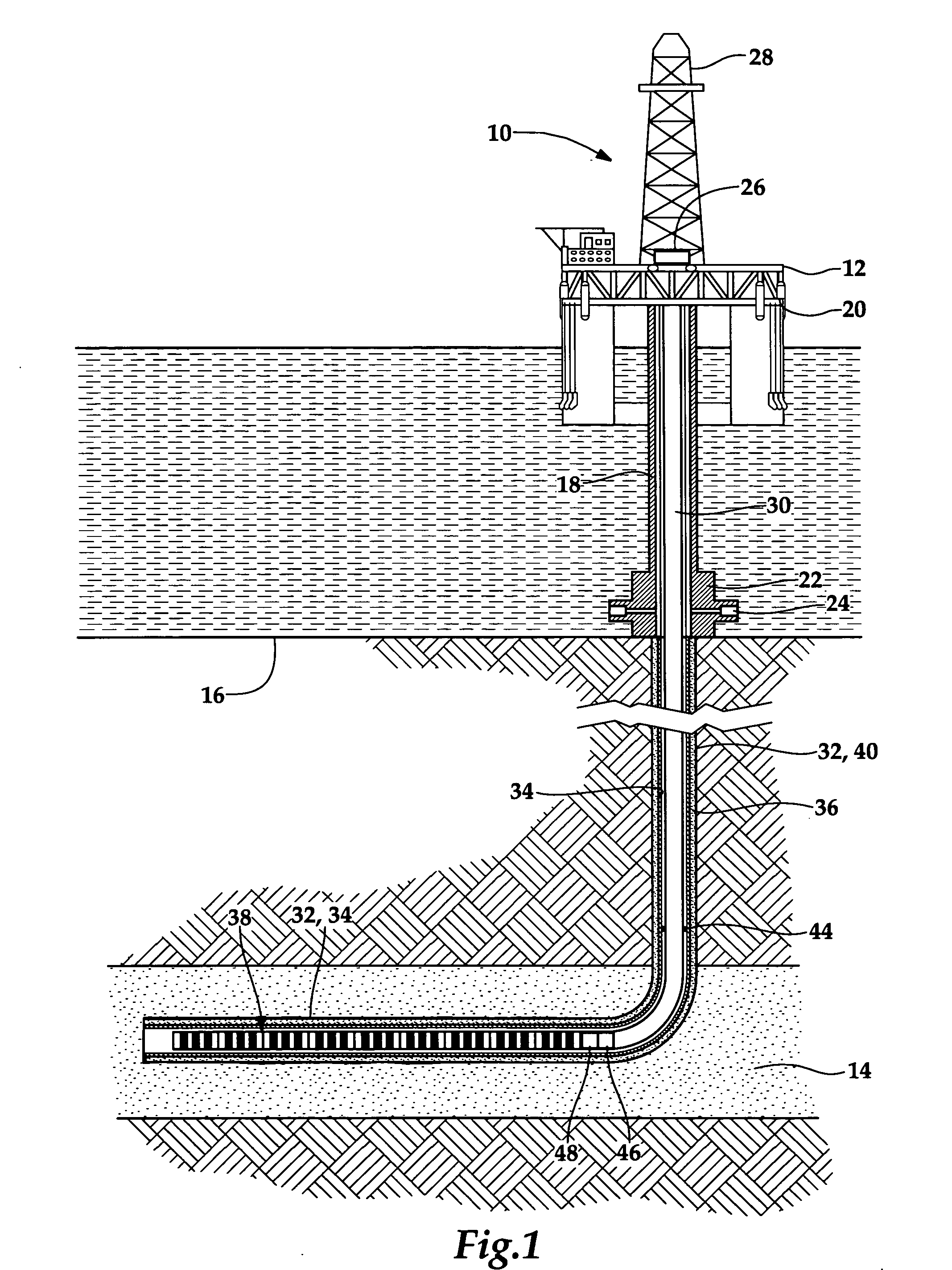
[0031] Referring initially to FIG. 1, a debris retention perforating apparatus operating from an offshore oil and gas platform is schematically illustrated and generally designated 10. A semi-submersible platform 12 is centered over a submerged oil and gas formation 14 located below sea floor 16. A subsea conduit 18 extends from deck 20 of platform 12 to wellhead installation 22 including subsea blow-out preventers 24. Platform 12 has a hoisting apparatus 26 and a derrick 28 for raising and lowering pipe strings such as work sting 30.

[0032] A wellbor...


PUM


Abstract

A perforating apparatus (100) includes a plurality of shaped charges (102) each having an initiation end and a discharge end. A detonating cord (116) is operably coupled to the initiation ends of the shaped charges (102). A carrier (106) contains the shaped charges (102). The carrier (106) includes at least one discharge location corresponding to the discharge ends of the shaped charges (102) when the perforating apparatus (100) is in its operable position. The discharge location has first and second material layers (122, 124) wherein the second material layer (124) exhibits resilient recovery such that an opening created by a jet formed from detonating one of the shaped charges (102) in the second material layer (124) is smaller than an opening created by the jet in the first material layer (122), thereby retaining debris in the perforating apparatus (100) with the second material layer (124).

Description

TECHNICAL FIELD OF THE INVENTION [0001] This invention relates, in general, to an apparatus for perforating a subterranean wellbore using shaped charges and, in particular, to a debris retention perforating apparatus that reduces the size of the holes made in the charge carrier upon detonation of the shaped charges thus enhancing debris containment. BACKGROUND OF THE INVENTION [0002] Without limiting the scope of the present invention, its background will be described with reference to perforating a subterranean formation with a shape charge perforating apparatus, as an example. [0003] After drilling the section of a subterranean wellbore that traverses a formation, individual lengths of relatively large diameter metal tubulars are typically secured together to form a casing string that is positioned within the wellbore. This casing string increases the integrity of the wellbore and provides a path for producing fluids from the producing intervals to the surface. Conventionally, the...

Claims


Application Information

Patent Timeline
Patent Type & Authority Applications(United States)
IPC IPC(8): B64D1/04
CPCE21B43/117
Inventor WALKER, JERRY L.
Owner HALLIBURTON ENERGY SERVICES INC
Learn More