Power-line communication device

a communication device and power line technology, applied in the direction of electric controllers, instruments, ignition automatic control, etc., can solve the problems of inability to ensure the space for providing all the above-described signal lines, the signal may not be correctly transmitted, and the use of serial communication becomes inadequate for reducing the number of signal lines. , to achieve the effect of reducing the number of signal lines

Inactive Publication Date: 2006-04-13
CANON KK
View PDF13 Cites 180 Cited by
  • Summary
  • Abstract
  • Description
  • Claims
  • Application Information

AI Technical Summary

Benefits of technology

[0009] The present invention is directed to a power-line communication device with a reduced number of signal lines used for performing communication between at least two units provided in a cabinet of an apparatus.

Problems solved by technology

As described above, the use of serial communication has become inadequate for reducing the number of signal lines.
Namely, it is difficult to ensure space for providing all of the above-described signal lines therein in confined spaces of a cabinet of the copier system.
In that case, however, a signal may not be correctly transmitted due to noise generated at the time where a switching element of the switching power supply is turned on and / or off.

Method used


Image

  • Power-line communication device
  • Power-line communication device
  • Power-line communication device

Examples


first embodiment

[0020] Hereinafter, embodiments of the present invention will be described in detail with reference to the attached drawings.

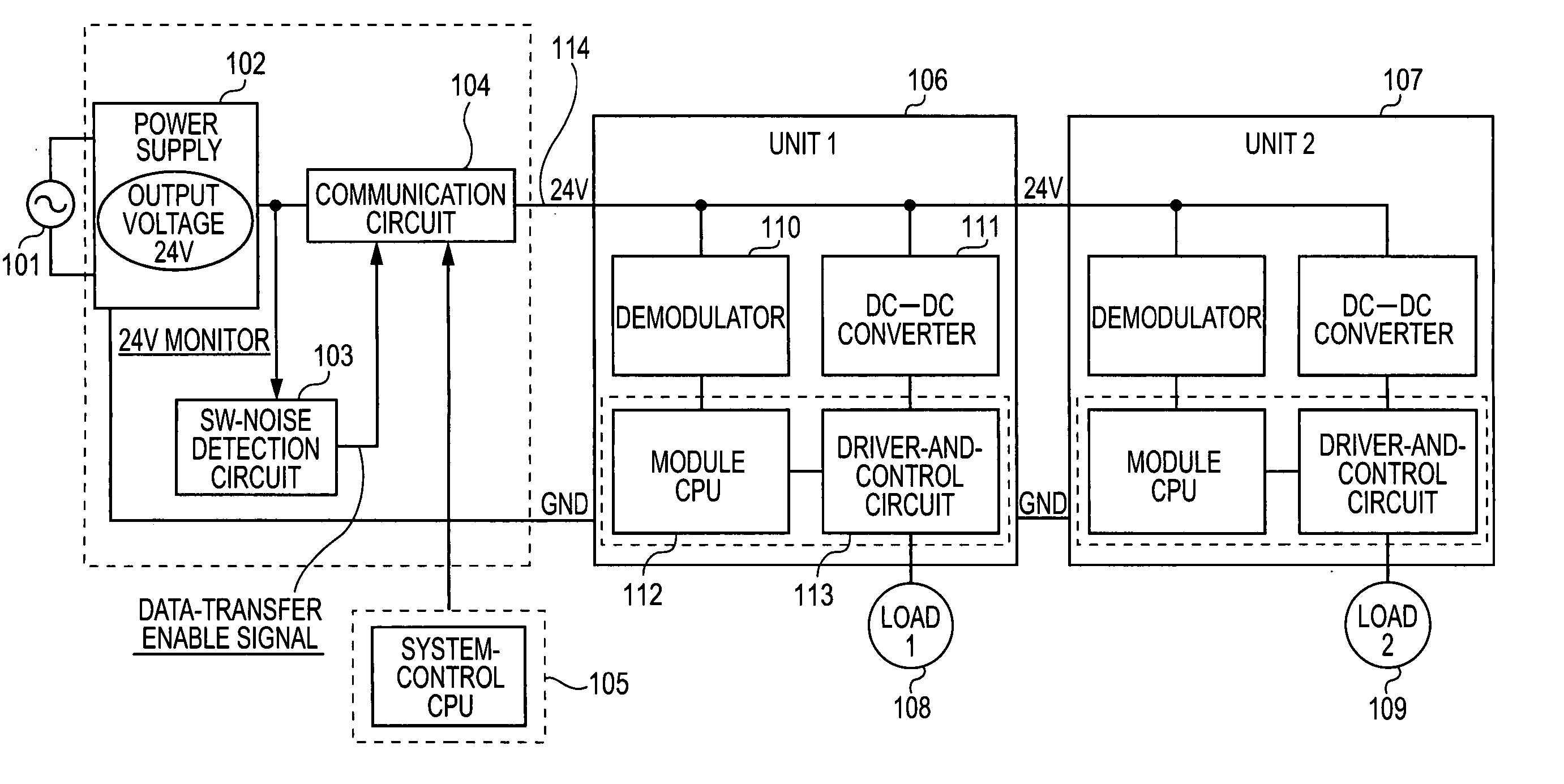
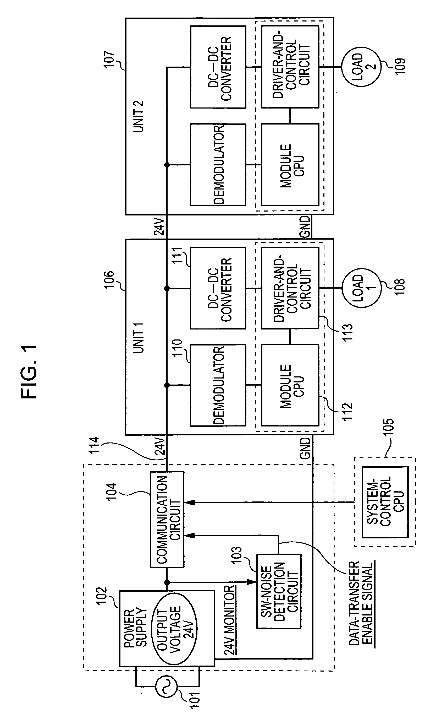
[0021]FIG. 1 is a block diagram illustrating a power supply and control units of an image-synthesis apparatus to which the present invention can be used.

[0022] AC power of a commercial power supply 101 is transmitted to a power supply 102 so that the image-synthesis apparatus can operate. An output voltage transmitted from the power supply 102 is fixed at about 24 V. The output voltage of the power supply 102 is commonly used, so as to drive first and second loads 108 and 109 such as motors of first and second units 106 and 107 provided in the image-synthesis apparatus, and / or control the units. An output end of the power supply 102 is connected to the units via a power line 114 of 24 V. Subsequently, the electric power of the power supply 102 is transmitted to the first unit 106 and the second unit 107.

[0023] A control signal is superimposed on the power l...

second embodiment

[0036] The configuration of the power supply 102 (switching power supply) will be described with reference to FIG. 3. Electric power is supplied from the commercial power supply 101 to the power supply 102. The electric power is transmitted to a first rectifying-and-smoothing circuit 302 via a filter 301 and converted into a DC voltage. The DC voltage is transmitted to one end of a primary winding of an insulating transformer 303. A resonant capacitor 305 and a switching (SW) element 304 are connected to the other end of the primary winding. When the SW signal is switched between the ON state and the OFF state, the switching element 304 is driven and an output voltage is generated at a secondary winding of the insulating transformer 303. The output voltage is rectified and smoothed into a DC voltage by a second rectifying-and-smoothing circuit 306 and externally transmitted from the power supply 102. For controlling the output voltage of the power supply 102, so as to be adjusted in...


PUM


Abstract

A power-line communication device in which a control signal is superimposed on a power line between a switching power supply and a unit to be controlled to which an output of the switching power supply is supplied, so that the control signal is transmitted to the unit. At the same time, a switching noise generated by the switching power supply is monitored and communication is started by using the switching noise, as a synchronizing signal. Subsequently, communication can be performed during the intervals between the switching noises so that erroneous signal detection is reduced.

Description

BACKGROUND OF THE INVENTION [0001] 1. Field of the Invention [0002] The present invention relates to a power-line communication device configured to perform power-line communications, so as to control an electronic apparatus by using a power line connecting a direct-current (DC) power supply configured to supply power for the electronic apparatus and a control circuit. [0003] 2. Description of the Related Art [0004] Hitherto, where a copier system includes units that require no high-speed data transfer, serial communication has been used for transferring data and controlling the units. The above-described technology is disclosed, for example, in Japanese Patent Laid-Open No. 11-284606.According to the above-described serial communication, signals transmitted and / or received include a signal indicating that the serial communication is started, a communication clock, transmission data, a latch signal, and so forth so that data can be transmitted with increased reliability. [0005]FIG. ...

Claims


Application Information

Patent Timeline
Patent Type & Authority Applications(United States)
IPC IPC(8): H04B3/54G05B11/01
CPCH04B3/54H04B2203/5416H04B2203/547H04B2203/5483H04B2203/5491
Inventor ENDO, SATOSHI
Owner CANON KK
Why Eureka
Try Eureka