Projection Device Having Single Light Valve

a projection device and light valve technology, applied in the direction of projectors, optics, instruments, etc., can solve the problems of poor color saturation of projected images, inability to adapt the foregoing projection device to various operation modes, etc., and achieve the effect of maintaining contras

Active Publication Date: 2006-04-13
AIXIN TECH
View PDF4 Cites 12 Cited by
  • Summary
  • Abstract
  • Description
  • Claims
  • Application Information

AI Technical Summary

Benefits of technology

[0018] In the foregoing projection device having single light valve, for example, it further includes a control unit to synchronously control the color production device, the light valve and the beam breaker module. The control unit includes, for example, a light valve driver, an actuator driver, and a color production device driver. Wherein, the light valve driver is electrically coupled with the light valve. In addition, the actuator driver and the actuator are electrically coupled, so as to control the beam breaking part. In addition, the color production device driver and the color production device driver are electrically coupled, wherein the light valve driver, the actuator driver and the color production device driver in synchronous use to control the light valve, the beam breaker module, and the color production device.
[0019] The invention uses the beam breaker module, which is disposed between the light source and the screen, and is on the light propagation path. This beam breaker module can break the light beam within a specific time period, according to the state of the color production device. Therefore, the projection device having single light valve can be used in various operation modes with capability of maintaining the contrast.

Problems solved by technology

However, since the spoke regions between each of the color filtering regions on the color wheel 132 have the noise light, the color saturation of the projected image would get worse.
Therefore, the foregoing projection device cannot be adapted to various operation modes, such as high image brightness or high color saturation, to always provide the better contrast.

Method used


Image

  • Projection Device Having Single Light Valve
  • Projection Device Having Single Light Valve
  • Projection Device Having Single Light Valve

Examples


Embodiment Construction

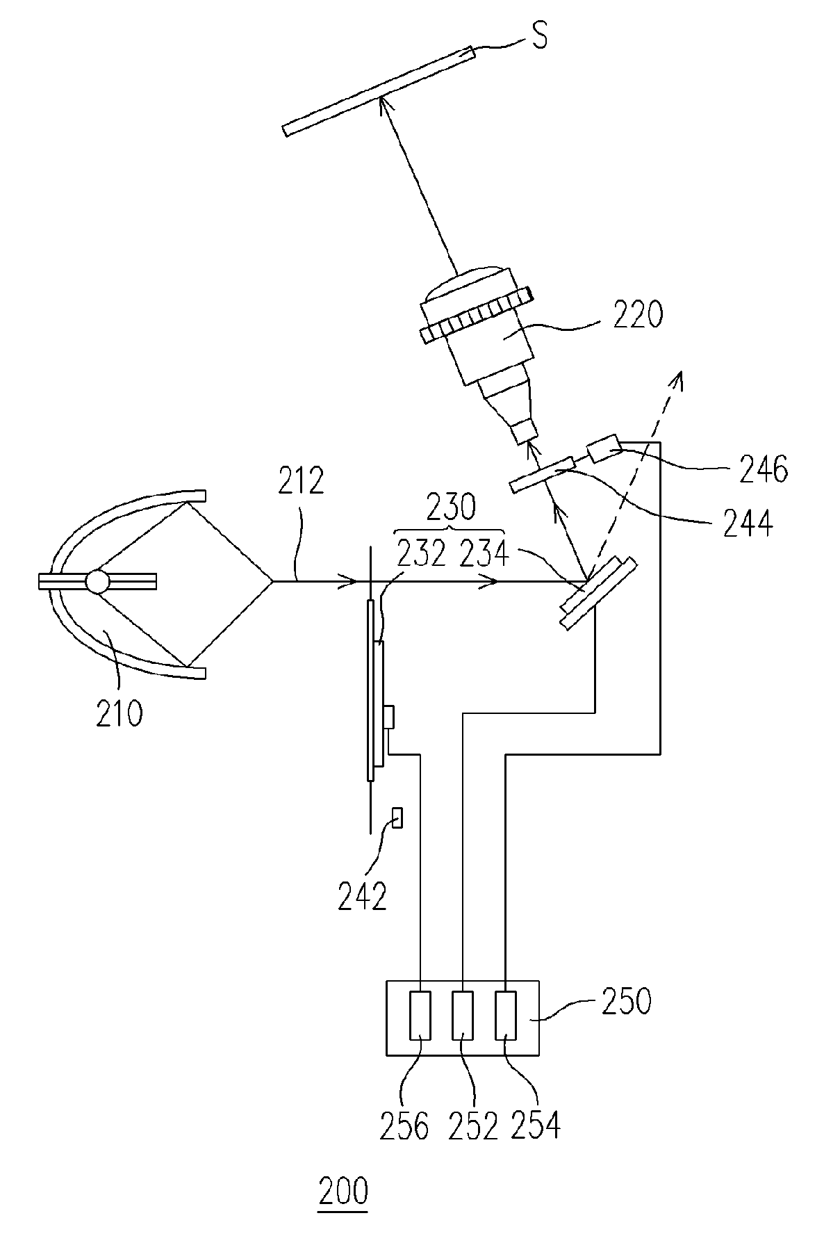
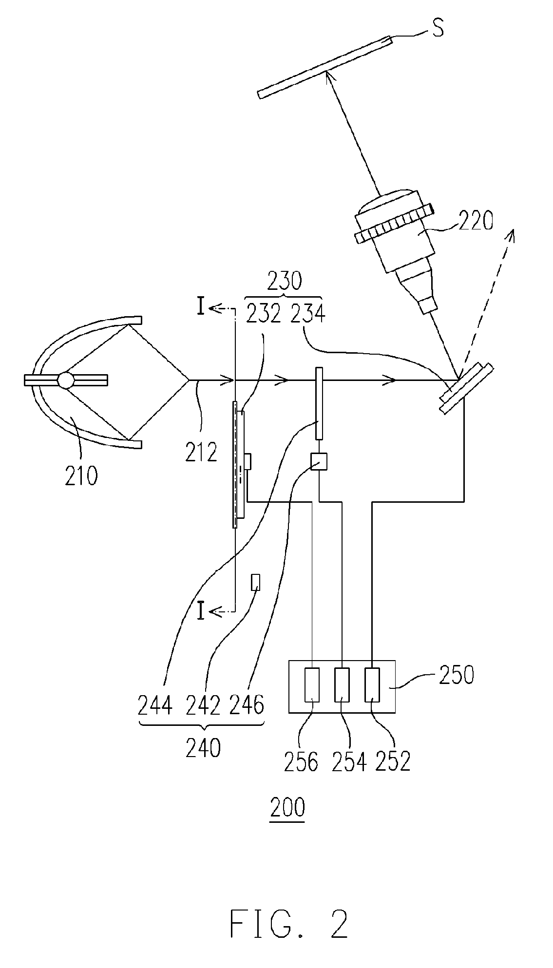
[0025]FIG. 2 is a drawing, schematically illustrating the structure of a projection device having single light valve, according to an embodiment of the present invention. In FIG. 2, the invention proposes a projection device having single light valve 200, which can project in image (not shown) to a screen S. The projection device having single light valve 200 includes a light source 210, a projection lens 220, an image unit 230, and a beam breaker module 240. In the foregoing projection device having single light valve 200, the light source 210 can provide a light beam 212. The projection lens 220 is disposed behind the light source 210, and is located on the propagation path of the light beam 212. In addition, the image init 230 is disposed between the light source 210 and the projection lens 220, and is located on the propagation path of the light beam 212.

[0026] In the embodiment of the invention, the image unit 230 includes, for example, a color production device 232 and a ligh...


PUM


Abstract

A projection device having single light valve has a light source, a projection lens, an imaging unit and a beam breaker. Moreover, the imaging unit has a color production device and a valve. When the beam provided by light source propagates to the color production device, the color production device converts the beam into several different color beams in an order. Thereafter, the beams propagate to the beam breaker, and the beam breaker breaks the beam propagating through within a definite time according to the states of imaging unit. Afterwards, the beams that are not broken are converted into images by the light valve in order, and projected on a screen by projection lens. The beam breaker module can enable the projection device having single light to have several situation modes, and maintain the imaging contrast.

Description

BACKGROUND OF THE INVENTION [0001] 1. Field of Invention [0002] The present invention relates to a projection device having single light valve. More particularly, the present invention relates to a projection device having single light valve, which can be operated under various operation modes with the effect of image contrast simultaneously. [0003] 2. Description of Related Art [0004] In recent years, the cathode ray tube (CRT) projection device, which has large volume and is heavy, has been gradually replaced by the products, such as the LCD projection device and digital light processing (DLP) projection device. These products has the characteristics of being light and portable, and can be directly coupled with the digital products, so as to display the image by projection. Under the situation that the manufacturers are continuously developing cheaper and competitive products with additional function, these products can not only be used in company, school, or a public area for bri...

Claims


Application Information

Patent Timeline
Patent Type & Authority Applications(United States)
IPC IPC(8): G03B21/14
CPCG03B21/14G02B26/008G03B21/005G03B33/08
Inventor WANG, SZE-KE
Owner AIXIN TECH
Why Eureka
Try Eureka