Apparatus to align stereoscopic display

a technology of stereoscopic display and apparatus, which is applied in the direction of optics, electrical apparatus, instruments, etc., can solve the problems of high inherent cost of alignment systems of this type, the inability to meet the needs of manufacturing facilities, and the inability to meet the needs of the manufacturing facility personnel, so as to achieve easy and inexpensive fabrication, assess and make adjustments quickly, and the effect of easy and inexpensive fabrication

Inactive Publication Date: 2006-04-13
EASTMAN KODAK CO
View PDF14 Cites 10 Cited by
  • Summary
  • Abstract
  • Description
  • Claims
  • Application Information

AI Technical Summary

Benefits of technology

[0020] It is an advantage of the present invention that it requires a small set of components and can be easily and inexpensively fabricated. No power connection or cabling would be required for its use.
[0021] It is a further advantage of the present invention that it is easy to use, enabling an operator to assess and make adjustments quickly.
[0022] It is a further advantage of the present invention that viewer-to-viewer eye angular position differences and angular drift between eyes with a single viewer are eliminated, because only one eye ...

Problems solved by technology

However, with pupil imaging systems in set (ii) defined above, alignment of components in left and right imaging channels proves to be much more complex.
While such a solution works, however, the inherent cost of an alignment system of this type is high.
Moreover, supporting apparatus needed for such an arrangement constrain the usefulness of such an approach, restricting its practical use to manufacturing facility personnel only.
Deployment of dual-camera alignment apparatus of this type for servicing equipment in the field would be prohibitively costly.
Although special test equipment is not needed, this method suffers from two drawbacks.
First, there can be angul...

Method used


Image

  • Apparatus to align stereoscopic display
  • Apparatus to align stereoscopic display
  • Apparatus to align stereoscopic display

Examples


Embodiment Construction

[0033] The present description is directed in particular to elements forming part of, or cooperating more directly with, apparatus in accordance with the invention. It is to be understood that elements not specifically shown or described may take various forms well known to those skilled in the art.

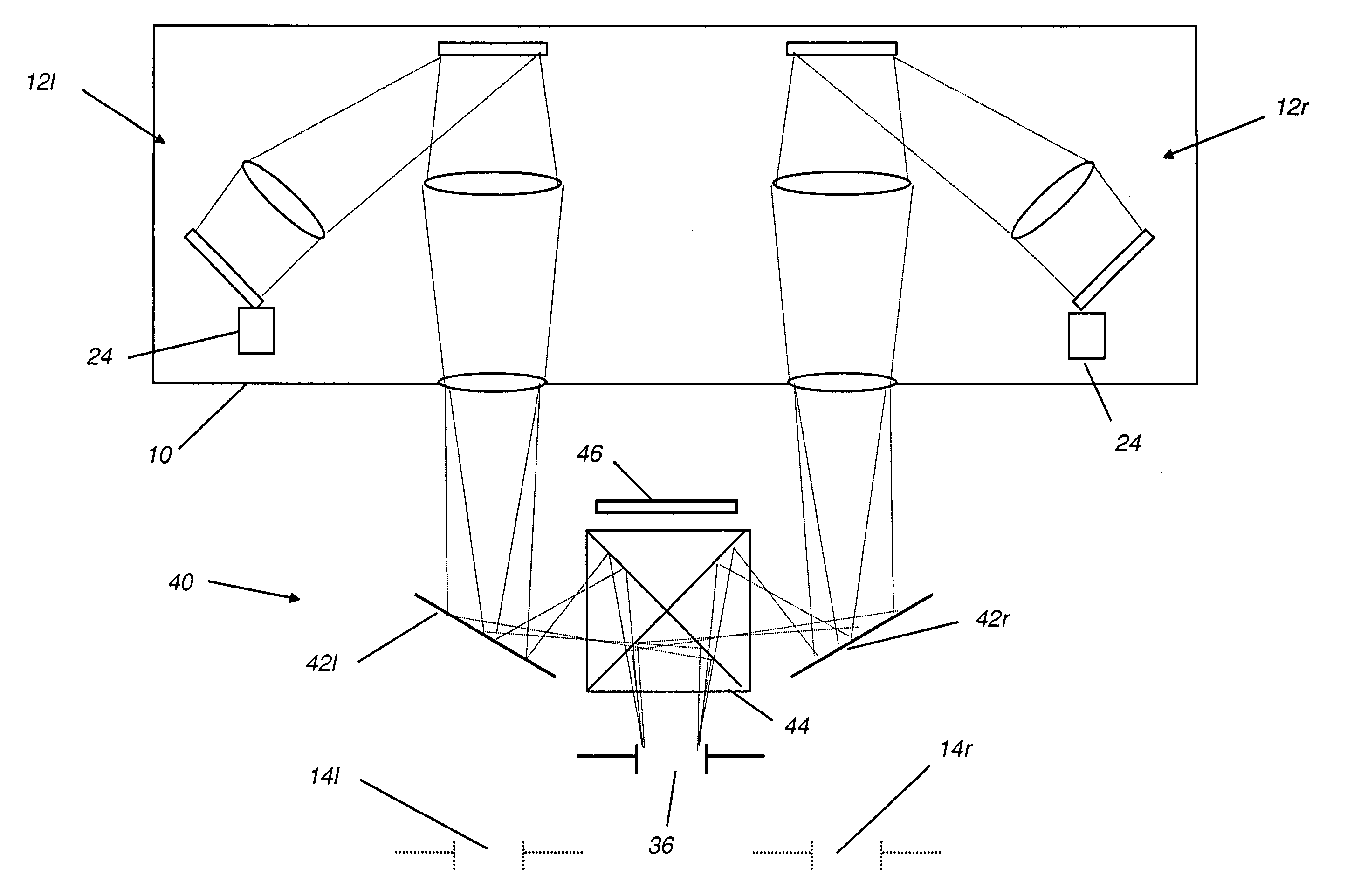
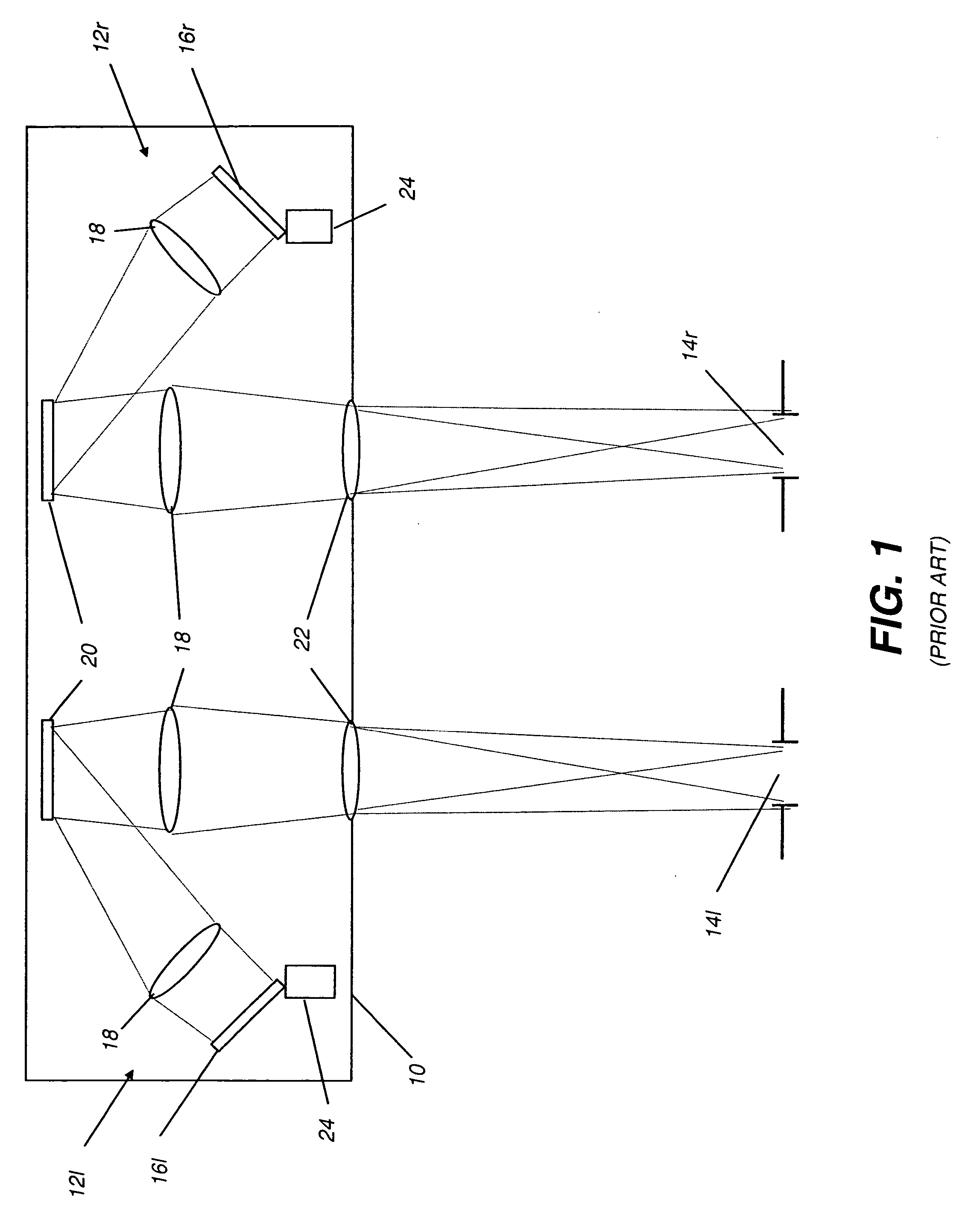
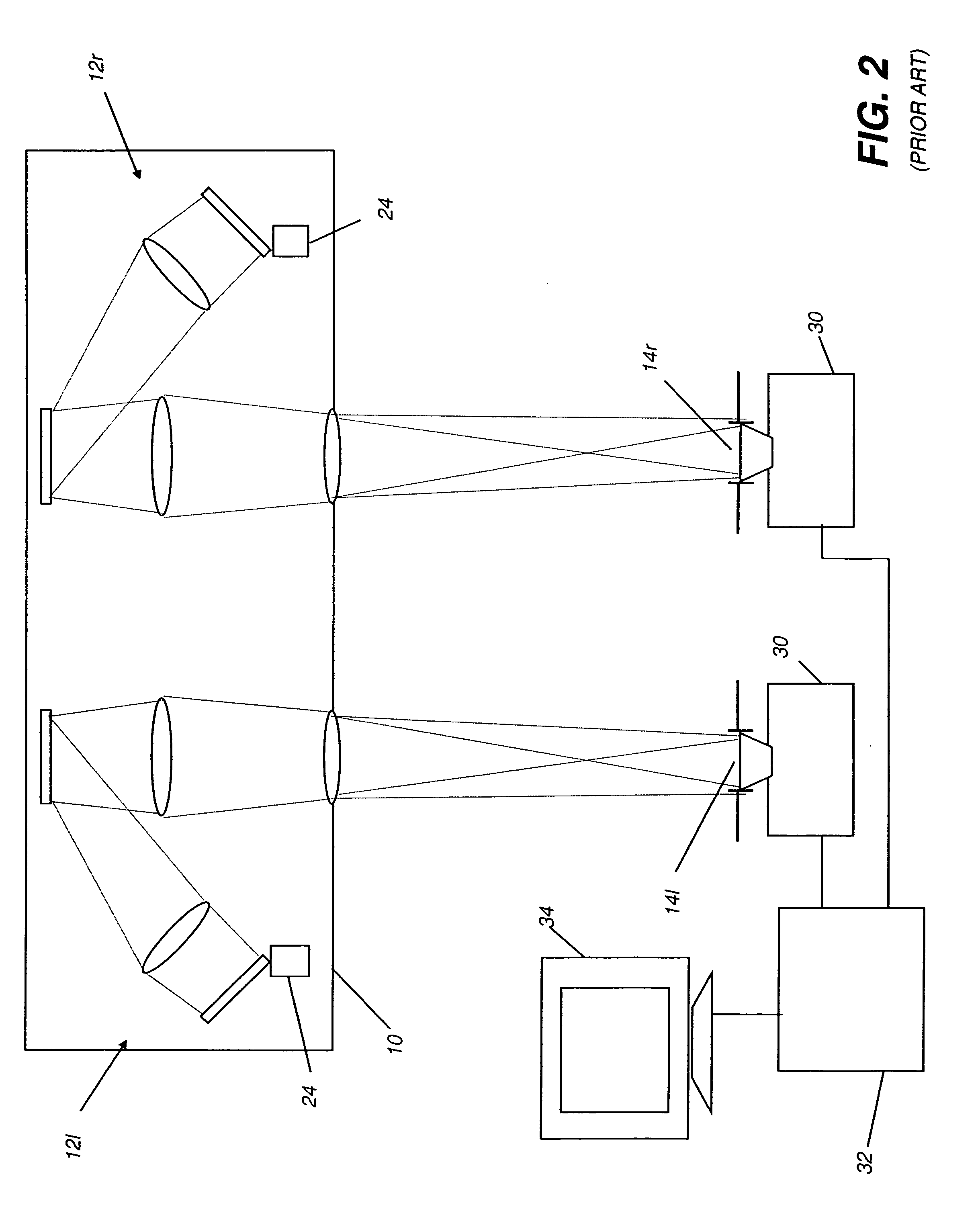
[0034] As was described with reference to FIG. 1, stereoscopic pupil imaging apparatus 10 forms left and right viewing pupils 14l and 14r at the position of the viewer. FIG. 3 shows an embodiment of the present invention in which an alignment viewer apparatus 40 redirects or diverts the light that had been projected to form left and right viewing pupils 14l and 14r (shown in phantom in FIG. 3) in order to form an alignment viewing pupil 36. Alignment viewing pupil 36 is thus formed by the combined modulated light from both left and right imaging channels 12l and 12r. A left mirror 42l directs light from left imaging channel 12l toward a beam combiner 44. Similarly, a right mirror 42r dir...


PUM


Abstract

An alignment viewer apparatus (40) for assessing optical path alignment of a stereoscopic imaging system (10), the apparatus (40) having a left reflective surface (42l) for diverting light from a left viewing pupil (14l) toward a beam combiner (44) and a right reflective surface (42r) for diverting light from a right viewing pupil (14r) toward the beam combiner (44). The beam combiner (44) directs the diverted light from left and right viewing pupils (14l and 14r) to form a combined alignment viewing pupil (36), allowing visual assessment of optical path alignment thereby.

Description

FIELD OF THE INVENTION [0001] This invention generally relates to stereoscopic display apparatus and more particularly relates to an apparatus and method for alignment of image path components in a stereoscopic display apparatus that presents spatially separate left and right images. BACKGROUND OF THE INVENTION [0002] The advantages offered by stereoscopic imaging are well recognized as useful in a number of applications, including medical imaging, flight simulation, and entertainment. In stereoscopic imaging, complementary left- and right-eye images are formed separately, typically in separate left and right channels, and are presented to the viewer to provide a composite image that is perceived as having enhanced depth and as being more realistic than are images conventionally projected over a single channel. [0003] A number of stereoscopic imaging approaches have been employed in various types of imaging systems. For example, some types of stereoscopic imaging systems use a proje...

Claims


Application Information

Patent Timeline
IPC IPC(8): G02B27/22G02B30/26
CPCG02B27/225H04N13/0425H04N13/327G02B30/20G02B30/26
Inventor COBB, JOSHUA M.RODDY, JAMES E.
Owner EASTMAN KODAK CO
Why Eureka
Try Eureka