Ultrasonic locating system

a technology of ultrasonic transmitter and base station, which is applied in the direction of measuring devices, instruments, and using reradiation, can solve the problems of difficult to determine the room in which an object is located without extensive calibration, and the cost per base station with antenna for the radio is substantially greater than the cost of ultrasonic transmitter, and achieves high data transfer capacity

Active Publication Date: 2006-04-13
SONITOR TECH
View PDF17 Cites 63 Cited by
  • Summary
  • Abstract
  • Description
  • Claims
  • Application Information

AI Technical Summary

Benefits of technology

[0011] The present invention relates to a method and a system for monitoring and position determination of identification tags which can be attached to objects. The object of the invention is to provide a flexible s...

Problems solved by technology

The area of application of this system is restricted, the system requires accurate location of all the receivers in advance and complicated signal processing, and it functions best when there is an unobstructed view between the transmitter and the receivers.
In practice, the accuracy of such a system will be a few...

Method used


Image

  • Ultrasonic locating system
  • Ultrasonic locating system
  • Ultrasonic locating system

Examples


Embodiment Construction

[0023] The system according to the invention is constructed in such a manner as to obtain high data transfer capacity and insensitivity to Doppler shift. There are several technical features with regard to transmitter, receiver and central unit that contribute to this. As a whole it represents a system that is well suited to different environments. The advantages of the invention are achieved by combining the use of radio waves with ultrasonic waves in the manner described below.

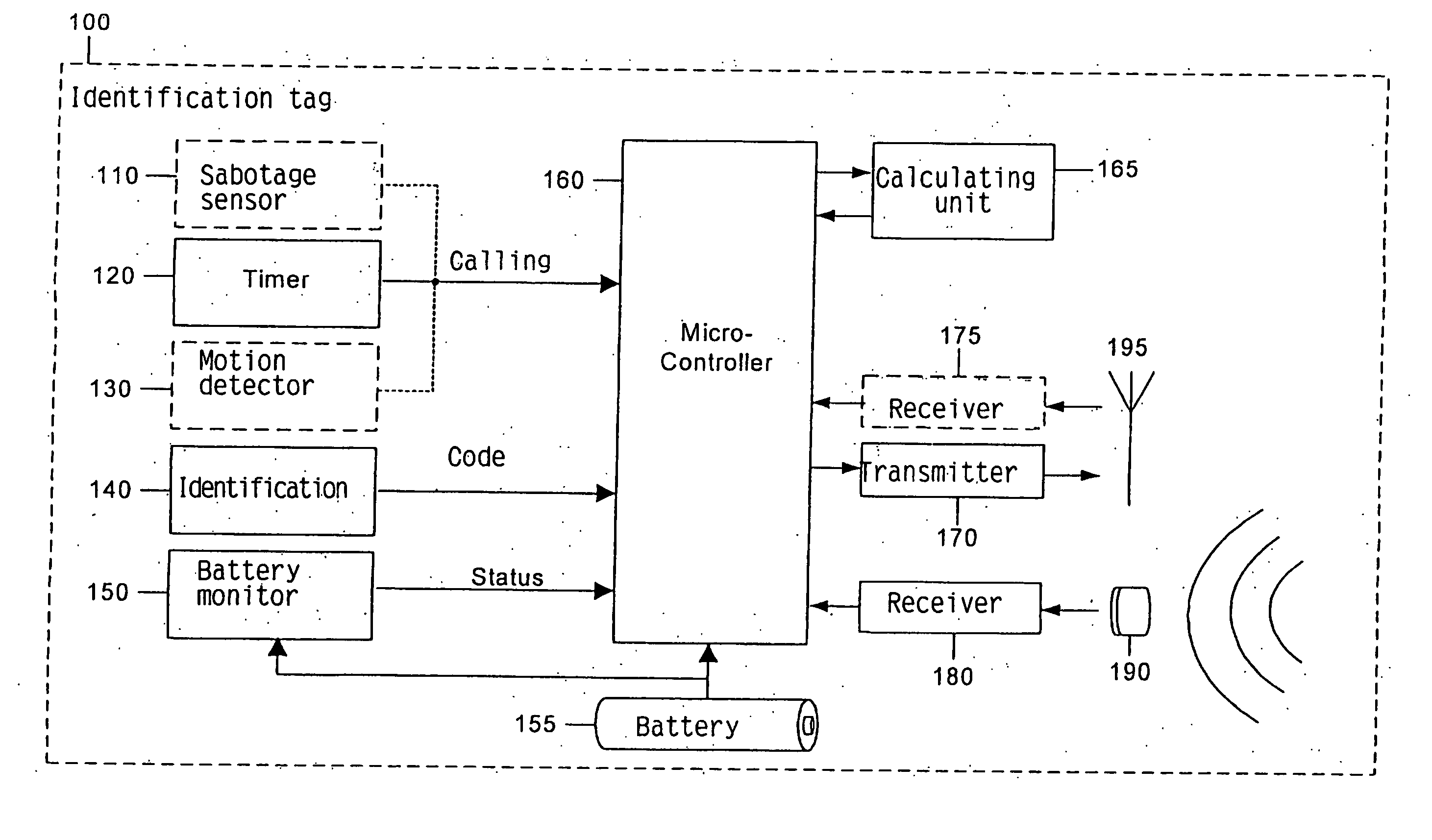
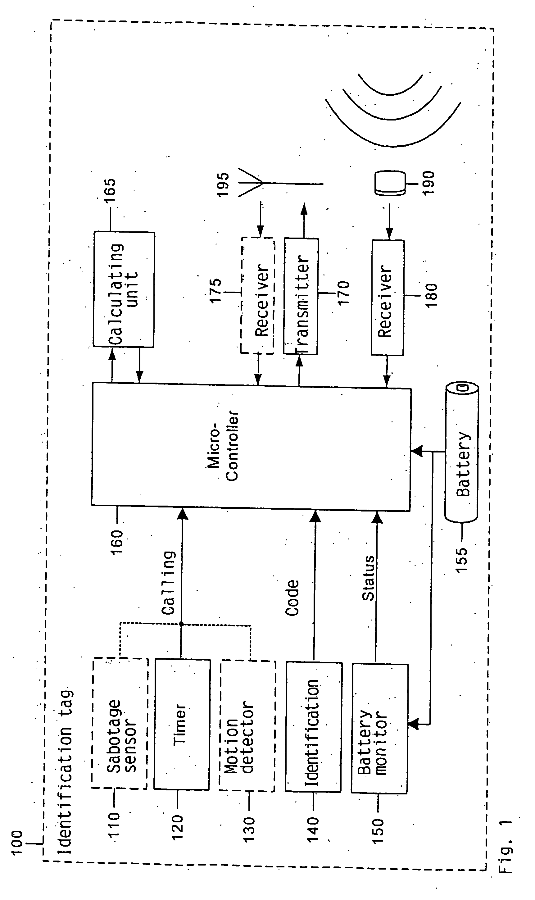
[0024]FIG. 1 illustrates which units may typically be incorporated in each identification tag 100. The identification tag 100, which is intended for use in a location system 400 (FIG. 3) for determining the identification tag's 100 location in a room in a building or areas that require to be monitored, comprises an ultrasonic transducer 190 adapted to receive ultrasonic signals, together with a radio transmitter 170 connected to an antenna 195 for transmitting signals with information containing the identit...


PUM


Abstract

The invention relates to a method and a system for monitoring and position determination of objects and/or living beings within an area, such as, e.g. a room in a building or a road tunnel. The system comprises a plurality of identification tags equipped with an ultrasonic receiver and radio transmitter which is attached to the objects that have to be monitored. The identification tags receive ultrasonic signals whose arrival time they measure. This information together with the identification tags'ID code are transmitted by radio waves to a central unit which calculates the position of each of the identification tags.

Description

INTRODUCTION / TECHNICAL FIELD [0001] The invention relates to a method and a system for monitoring and position determination of objects and / or living beings within an area such as, e.g. a room in a building or a road tunnel. The system comprises a plurality of electronic units called identification tags, which are attached to the objects to be monitored. Each identification tag has its own identification code (ID code) and is equipped with an ultrasonic receiver and radio transmitter. The ultrasonic signals it receives are transmitted synchronously from a plurality of transmitter units. The ultrasonic receiver in the identification tag is connected with a calculating unit which calculates the arrival time of received ultrasonic signals. This information together with the identification tag's ID code and any additional information are transmitted in the form of radio waves to a central processing unit which calculates the identification tag's position and presents it to a user of the...

Claims


Application Information

Patent Timeline
IPC IPC(8): G01S3/808G01S5/30G01S11/14G01SG01S5/00G01S5/26
CPCG01S5/0036G01S5/26
Inventor HOLM, SVERRE
Owner SONITOR TECH
Why Eureka
Try Eureka