
Solid immersion lens, focusing lens using solid immersion lens, optical pickup apparatus, optical recording reproducing apparatus and method of manufacturing solid immersion lens

a technology of solid immersion lens and focusing lens, which is applied in the field of solid immersion lens, focusing lens using solid immersion lens, optical pickup apparatus, optical recording reproducing apparatus and method of manufacturing solid immersion lens, can solve the problems of reducing aperture na, unavoidable shape limitation of focusing lens, and reducing the bonding area of solid immersion lens with lens holding member, etc., to achieve more stably, more stable, and more stable transportation

Inactive Publication Date: 2006-04-13
SONY CORP
View PDF8 Cites 20 Cited by
  • Summary
  • Abstract
  • Description
  • Claims
  • Application Information

AI Technical Summary

Benefits of technology

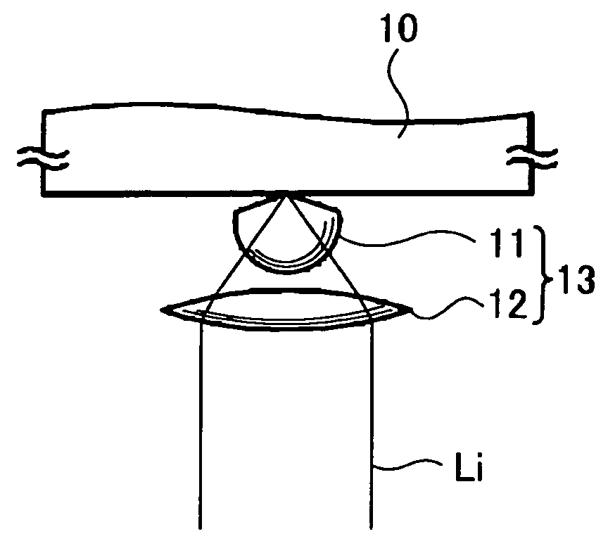
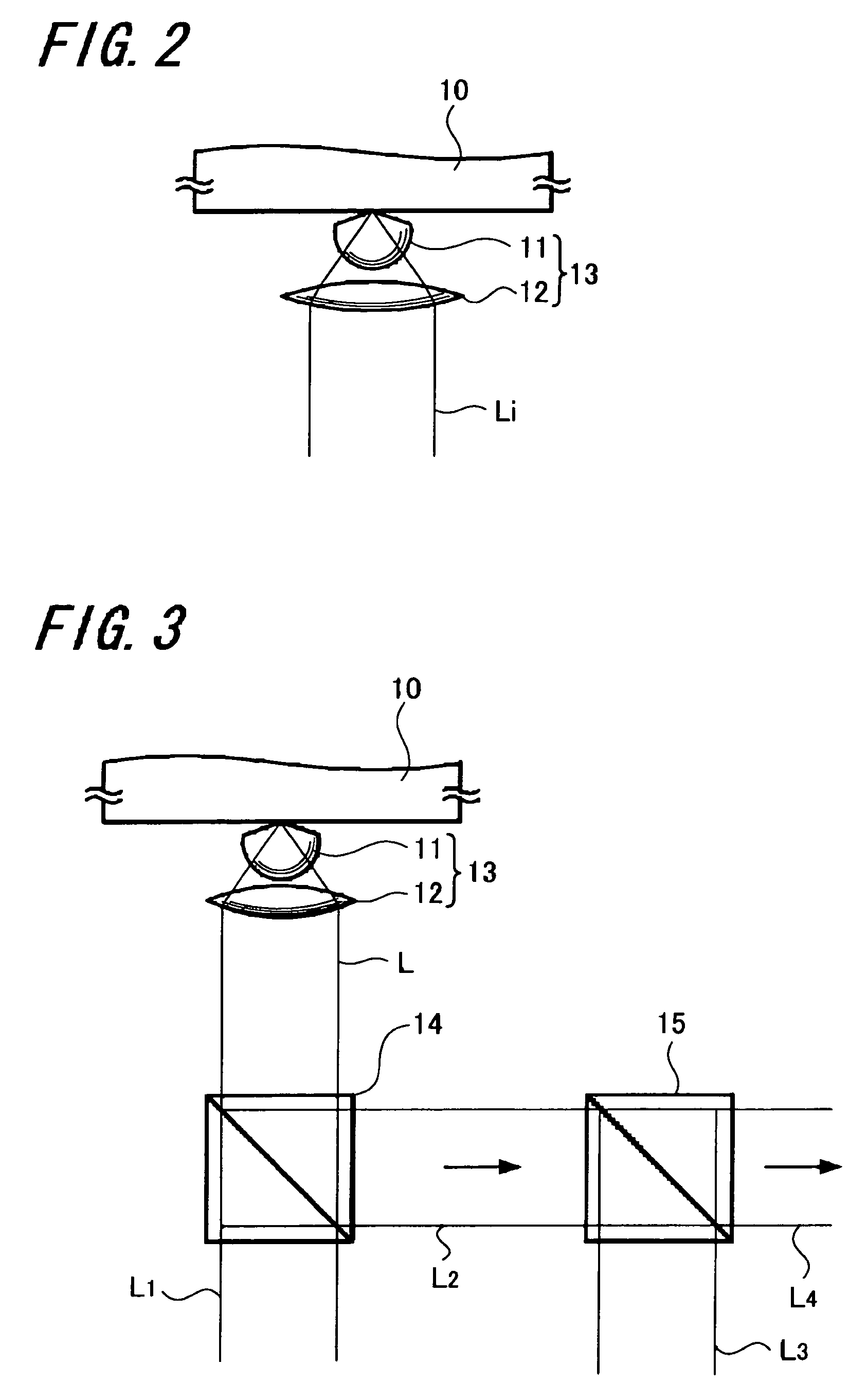
[0024] As described above, according to the solid immersion lens of the present invention, since the protrusive convex portion is provided on the object side of the solid immersion lens and the difference-in-level portion or the concave portion is provided at least on a part of this convex portion, the bonding area with the lens holding member can be increased and hence the solid immersion lens can be held by the lens holding member more stably as compared with the related art.
[0025] Further, according to the focusing lens, the optical pickup apparatus and the optical recording and reproducing apparatus of the present invention, the solid immersion lens for use with the focusing lens can be held stably and hence it is possible to provide an optical pickup apparatus and an optical recording and reproducing apparatus which can be stably transported relative to the optical recording medium by using the solid immersion lens with the large numerical aperture.
[0026] Furthermore, according to a method of forming a solid immersion lens of the present invention, a solid immersion lens which can stably be held comparatively can be formed with high accuracy without exerting an influence on incident light.

Problems solved by technology

Also, since a diameter of a bundle of light introduced into the focusing lens from the light source is reduced and the distance between the optical recording medium and the focusing lens is reduced to become very small, which is less than approximately several 10 s of nanometers, an inclination margin between the optical recording medium and the focusing lens, that is, so-called can become very small and hence it is unavoidable that the focusing lens is largely restricted from a shape standpoint.
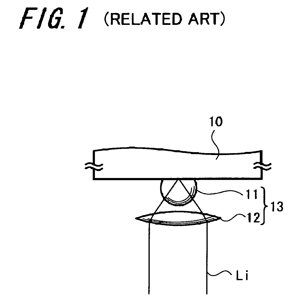
As a result, a bonding area of the solid immersion lens with a lens holding member for holding a solid immersion lens with a large numerical aperture NA is decreased, and there is a risk that the lens holding member will be detached from the solid immersion lens with application of a very small shock.

Method used


Image

  • Solid immersion lens, focusing lens using solid immersion lens, optical pickup apparatus, optical recording reproducing apparatus and method of manufacturing solid immersion lens
  • Solid immersion lens, focusing lens using solid immersion lens, optical pickup apparatus, optical recording reproducing apparatus and method of manufacturing solid immersion lens
  • Solid immersion lens, focusing lens using solid immersion lens, optical pickup apparatus, optical recording reproducing apparatus and method of manufacturing solid immersion lens

Examples


##ventive example 1

INVENTIVE EXAMPLE 1

[0113] As a solid immersion lens, a high refractive index glass material of S-LAH79 (trade name) made by OHARA INC., was used and as FIG. 17 shows a schematic arrangement, there was manufactured a solid immersion lens of the inventive example 1 in which the radius r of the solid immersion lens 11 was selected to be 0.45 mm, its thickness r (1+1 / n) was selected to be 0.667 mm and the convex portion 2 on the objective side was shaped as a circular cone with an inclination angle of 20 degrees relative to the objective surface 3. At that time, the radius d of the objective surface 3 was selected to be 20 μm.

[0114] In this inventive example 1, while the height x from the objective surface 3 to the edge portion 4 of the spherical portion 1 was 155.0 μm, the height xi from the objective surface 3 to the incident position of the incident light Li was 216.6 μm. Accordingly, a very small concave portion shown in FIG. 12 was formed by cutting the portion of 61.6 μm of the d...

##ventive example 2

INVENTIVE EXAMPLE 2

[0115] Next, the inventive example 2 will be described. As a solid immersion lens, a high refractive index glass material of S-LAH79 (trade name) made by OHARA INC., was used and as shown in FIG. 18, there was manufactured a solid immersion lens of the inventive example 2 in which the radius r of the solid immersion lens 11 was selected to be 0.45 mm, its thickness r (1+1 / n) was selected to be 0.667 mm and the convex portion 2 on the objective side was shaped as a circular cone with an inclination angle of 10 degrees relative to the objective surface 3. At that time, the radius d of the objective surface 3 was selected to be 20 μm.

[0116] At that time, while the height x from the objective surface 3 to the edge portion 4 of the spherical portion 1 was 71.6 μm, the height xi from the objective surface 3 to the incident position of the incident light Li was 130 μm. Accordingly, a difference-in-level shape shown in FIG. 16 was formed by processing the portion of 58.4...


PUM


Abstract

A convex portion is provided on the objective side of a solid immersion lens so as to protrude toward an optical recording medium and a difference-in-level portion or a concave portion is provided at least on a part of this convex portion. Then, there are provided a solid immersion lens for satisfactorily holding the bonding state of a lens holding member, a focusing lens using this solid immersion lens, an optical pickup apparatus, an optical recording and reproducing apparatus and a method of forming a solid immersion lens.

Description

CROSS REFERENCES TO RELATED APPLICATIONS [0001] The present invention contains subject matter related to Japanese Patent Application JP 2004-267397 filed in the Japanese Patent Office on Sep. 14, 2004, Japanese Patent Application JP 2005-045736 filed in the Japanese Patent Office on Feb. 22, 2005, the entire contents of which being incorporated herein by reference. BACKGROUND OF THE INVENTION [0002] 1. Field of the Invention [0003] The present invention relates generally to a solid immersion lens (SIL), a focusing lens using such solid immersion lens, an optical pickup apparatus, an optical (or magneto-optical) recording and reproducing apparatus and a method of forming a solid immersion lens. More particularly, the present invention relates to a solid immersion lens suitable for use with a so-called near field optical recording and reproducing system in which a numerical aperture of a focusing lens is increased by using a material in which an optical lens has a large refractive ind...

Claims


Application Information

Patent Timeline
IPC IPC(8): G11B7/00
CPCG11B7/1374G11B2007/13727G02B13/00
Inventor SHINODA, MASATAKA
Owner SONY CORP
Learn More