
Cervical Immobilization Collar with Arterial Cooling Elements

a technology of immobilization collar and cooling element, applied in the field of cervical immobilization and to the therapeutic induction of mild cerebral hypothermia, can solve the problems of brain injury, long-term treatment or care, long-term damage, etc., and achieve the effect of reducing the chance of lasting brain damage and mitigate brain injuries

Inactive Publication Date: 2006-04-13
HEART CORE
View PDF25 Cites 17 Cited by
  • Summary
  • Abstract
  • Description
  • Claims
  • Application Information

AI Technical Summary

Benefits of technology

[0006] The invention among its preferred embodiments includes new procedures for first responders to mitigate brain injuries and new apparatus for inducing brain cooling within cervical immobilization collars used to stabilize patients for transport. Patients at risk of almost any sort of injury are routinely fitted with cervical immobilization collars for transport, and the invention incorporates heat extractors within the immobilization collars in positions for conducting heat from one or preferably both carotid arteries. With the modified immobilization collars, first responders can induce a mild cerebral hypothermia in patients both with and without obvious signs of brain insults or injuries. Those without any sort of brain insult or injury suffer no ill consequences, but those with brain insults or injuries enjoy neuroprotective effects that lessen the chances for lasting brain damage.
[0012] Another version of the invention as a protocol for treating trauma patients includes installing a cervical immobilization collar around a patient's neck having facility for limiting rotation and compaction of the patient's cervical vertebrae. At least one activatable cooling element carried by the collar is arranged in thermal transcutaneous communication with at least one of the patient's carotid arteries through an anterior portion of the patient's neck. The at least one activatable cooling element is activated in association with the installation of the collar, thereby initiating a flow of heat from the one or more carotid arteries through the anterior portion of the patient's neck to the cooling element for reducing the temperature of the patient's brain without inducing systemic hypothermia.
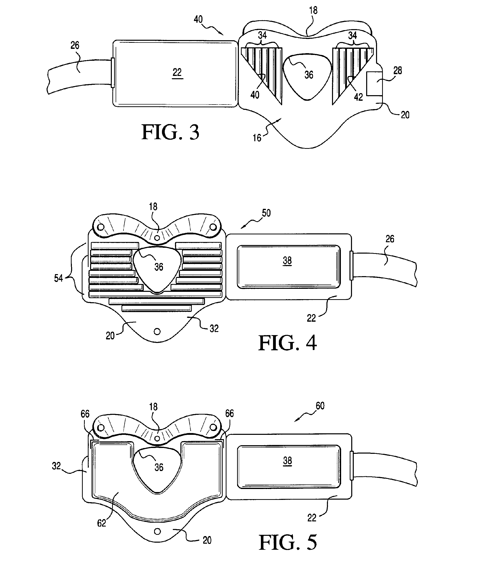
[0018] With the pad mounted on the inside surface of the support structure, the collar functions as a conventional cervical immobilization collar for stabilizing a wearer's cervical vertebrae. However, if brain injury is suspected, the pad can be removed and replaced by the cooling element for inducing a mild cerebral hypothermia while still providing similar cervical stabilization. The cooling element preferably includes reactants for an exothermic reaction and has a ribbed form to limit redistribution of the reactants.

Problems solved by technology

Brain injuries, such as those produced by blunt trauma or ischemic attack, can produce lasting damage and require long-term treatment or care.
Often, brain injuries produced by blunt trauma are suffered by the young, and any resulting disabilities or conditions can be expensive to treat and can require long-term care lasting nearly a lifetime.
Brain injuries in general are expensive to treat, but lasting injuries, especially in the young, can impose significant societal burdens.
Although the neuroprotective effects of even mild cerebral hypothermia have been well documented, along with the importance of initiating such cooling as soon as possible following a brain injury, protocols for first responders generally do not incorporate effective procedures for initiating brain cooling.
For example, blunt head trauma is often associated with the risk of cervical injury, and the routine application of conventional cervical immobilization collars can block effective cooling of neck tissue close to the carotid arteries.
Even if early brain cooling is a treatment option for cases of obvious blunt head trauma, other brain injuries can be difficult to detect on site, especially if there are few outward signs or the inflammatory response is slow to develop.

Method used


Image

  • Cervical Immobilization Collar with Arterial Cooling Elements
  • Cervical Immobilization Collar with Arterial Cooling Elements
  • Cervical Immobilization Collar with Arterial Cooling Elements

Examples


Embodiment Construction

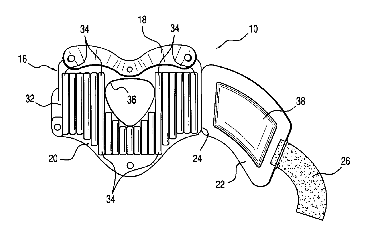
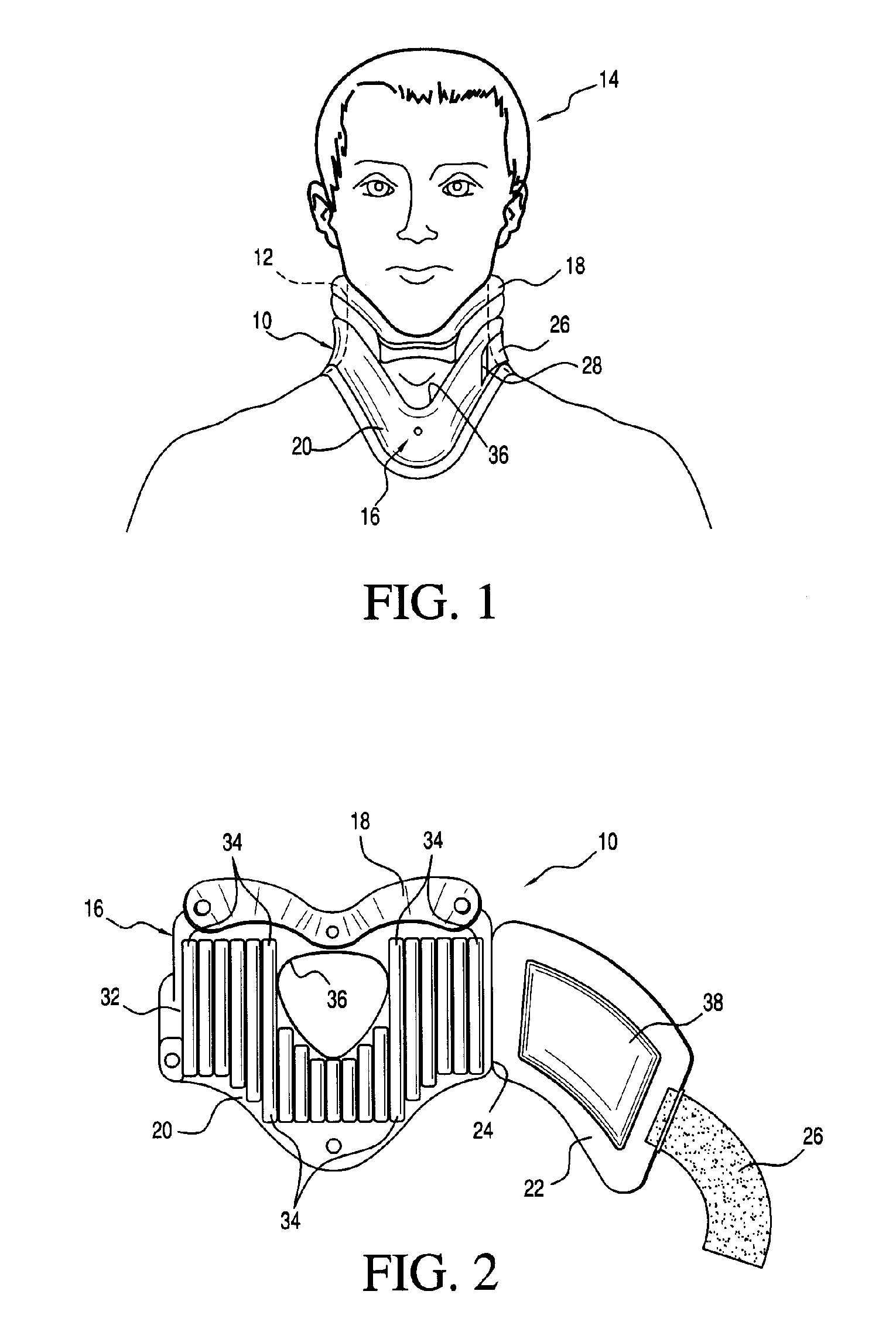
[0030] A cervical immobilization collar 10 in accordance with the invention is shown in FIG. 1 mounted in place about the neck 12 of a patient or other wearer 14 for purposes of both cervical spine immobilization and transcutaneous cooling of blood flowing through the wearer's carotid arteries. A support structure of the collar 10 includes a main body 16 having an extended axial length that limits cervical compaction of the wearer's neck 12 and a chin rest 18 for limiting cervical rotation of the wearer's neck 12.

[0031] Referring also to FIG. 2, the main body 16 includes an anterior portion 20 and a posterior portion 22. One end of the anterior portion 20 is connected to one end of the posterior portion 22 by an integral joint 24 or other preferably permanent connection. The main body can be formed (preferably by molding) from a variety of materials including plastics, polymers, or carbon or poly-paraphenylene terephthalamide fiber. A hook and loop fastener strap 26 extends from th...


PUM


Abstract

A cervical immobilization collar incorporates one or more cooling elements for inducing a mild cerebral hypothermia by transcutaneous cooling of oxygenated blood flowing through carotid arteries. The immobilization collar includes an annular support structure having an extended axial length for limiting cervical compaction of a wearer's neck and a chin rest for limiting cervical rotation of the wearer's neck. In addition, the one or more cooling elements, which function as a heat extractor, are carried by the support structure in positions for inducing transcutaneous conduction of heat through an anterior portion of the wearer's neck from at least one of the wearer's carotid arteries.

Description

TECHNICAL FIELD [0001] The invention integrates technologies relating to cervical immobilization and to therapeutic induction of mild cerebral hypothermia by transcutaneous cooling of oxygenated blood flowing through carotid arteries. BACKGROUND OF THE INVENTION [0002] Brain injuries, such as those produced by blunt trauma or ischemic attack, can produce lasting damage and require long-term treatment or care. Often, brain injuries produced by blunt trauma are suffered by the young, and any resulting disabilities or conditions can be expensive to treat and can require long-term care lasting nearly a lifetime. Brain injuries in general are expensive to treat, but lasting injuries, especially in the young, can impose significant societal burdens. [0003] Brain cooling, i.e., reducing brain temperatures by as little as one or two degrees Celsius, produces a neuroprotective effect against deleterious responses associated with brain injuries. The mild cerebral hypothermia inhibits the rele...

Claims


Application Information

Patent Timeline
Patent Type & Authority Applications(United States)
IPC IPC(8): A61F5/00
CPCA61F5/055Y10S128/23
Inventor SANDHU, AQEEL A.
Owner HEART CORE
Learn More