Device, method and arrangement for pressing two axis-parallel rollers approachable to one another in a device for producing and/or treating a web of material

a technology of two axis parallel rollers and a pressing device, which is applied in the direction of pressing section, transportation and packaging, web handling, etc., can solve the problems of more expensive and difficult roll production, and achieve the effect of less expensive and less complicated roll production

Inactive Publication Date: 2006-04-20
VOITH PATENT GMBH
View PDF8 Cites 8 Cited by
  • Summary
  • Abstract
  • Description
  • Claims
  • Application Information

AI Technical Summary

Benefits of technology

[0007] According to a first aspect of the present invention, the sensor elements are arranged in the force transmission path running from the force-producing elements via the rolls, outside roll bodies of the two rolls. As a result of displacing the sensor elements out of the roll bodies of the rolls, the production of the rolls is less complicated and less expensive. Since no sensors have to be embedded in the roll bodies, this opens up the possibility of using standard rolls. In addition, the occasional grinding of the rolls can in this way be performed without any regard to the sensor elements. Nevertheless, the pressure prevailing between the rolls can continue to be measured directly, since the sensor elements are arranged in the transmission path of the pressing force.
[0010] In the event that a plurality of parallel force transmission paths are provided for the force provided by the force-producing elements, then there is an advantageous possibility of influencing the effective pressing force between the rolls, in that the ratio of the forces transmitted via the various force transmission paths can be varied. For this purpose, stop elements which can be adjusted in order to change the ratio of the forces transmitted via the various force transmission paths are arranged in the further force transmission path.
[0011] In principle, it is sufficient to measure the force transmitted only at one point along the force transmission path running via the rolls. This point can be located upstream of the roll body of a first following one of the two rolls or downstream of the roll body of a second following one of the two rolls. However, it is also possible to perform a force measurement simultaneously at a plurality of points along the force transmission path running via the rolls. For this purpose, the sensor elements can include at least one sensor which is arranged upstream of the roll body of the first following roll and at least one sensor arranged downstream of the roll body of the second following roll. It is advantageous in this case that the measured values supplied by the various sensors can be compared with one another, so that the sensors, so to speak, monitor one another. The reliability and accuracy of the force measurement can be increased in this way.
[0015] Furthermore, additionally or alternatively to the possible sensor locations indicated above, the sensor elements can include at least one sensor which is accommodated in a separately produced sensor module, this sensor module being built in between the stand or the bearing lever and a bearing kit for a bearing journal of the roll held on the stand or the bearing lever. Such sensor modules are commercially available in the form of mechanically self-contained sealed force-measuring cells. For the mounting of the rolls, it is then possible to fall back on standard, standardized bearing kits, which has a cost-reducing effect.
[0022] Embedding pressure sensors in one of the rolls is not necessary in the solution according to the present invention. Therefore, recourse can be had to current standard rolls, which are considerably less costly. In addition, the occasional grinding of the rolls can be carried out without difficulty and without there being the danger of damaging sensors embedded in the rolls as a result of this grinding.

Problems solved by technology

Although the line pressure between the rolls can be registered very accurately in this way and, in the event of deviations from the desired values, appropriate activation of suitable force devices can be carried out in order to effect more intense or less intense pressing of the rolls, embedding the sensors in the roll body admittedly has the disadvantage that this makes the production of the roll more difficult and more expensive.

Method used


Image

  • Device, method and arrangement for pressing two axis-parallel rollers approachable to one another in a device for producing and/or treating a web of material
  • Device, method and arrangement for pressing two axis-parallel rollers approachable to one another in a device for producing and/or treating a web of material
  • Device, method and arrangement for pressing two axis-parallel rollers approachable to one another in a device for producing and/or treating a web of material

Examples


Embodiment Construction

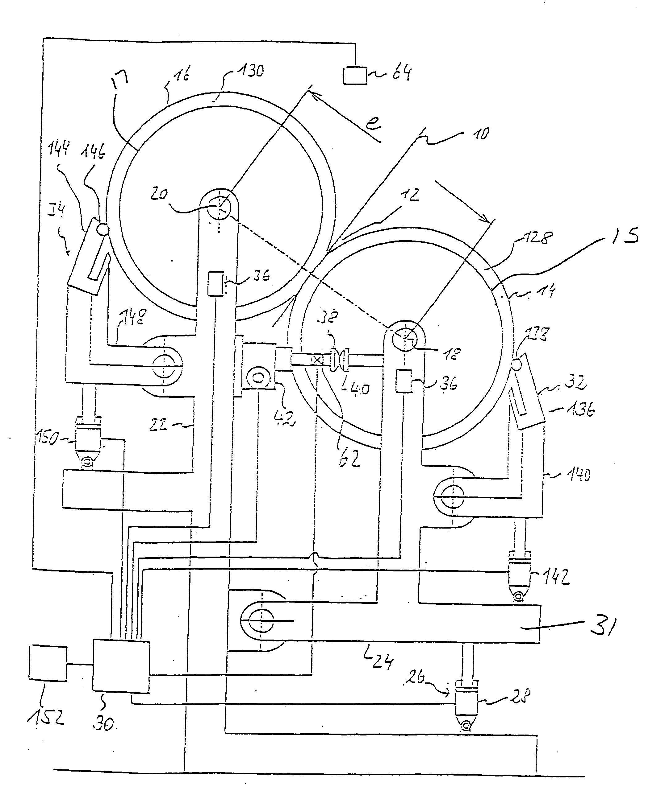
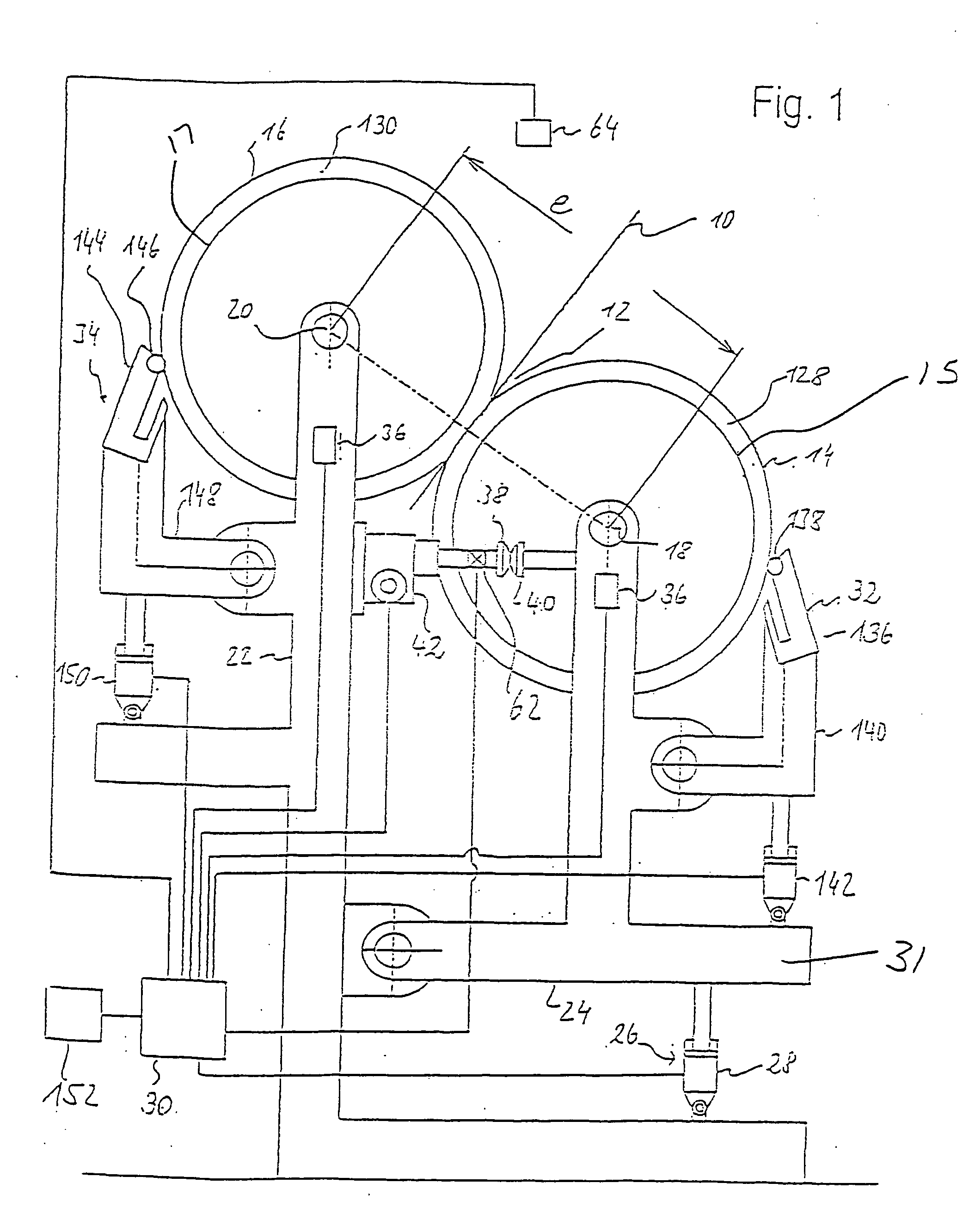
[0043] Referring now to the drawings, and more particularly to FIG. 1, there is shown a coating unit that is used for the indirect application of a liquid to pasty application medium, for example a pigment-containing coating color or a surface size, to both sides of a moving material web 10 of paper or board. Material web 10 moves through application gap 12, designated a nip in technical language, which is formed between two adjacently arranged rolls 14, 16 including roll bodies 15, 17, respectively. Roll bodies 15, 17 include the cylindrical portion of rolls 14, 16 and can also include covers 128, 130 on rolls 14, 16. Rolls 14, 16 are arranged with their axes 18, 20 parallel to each other. One of the rolls, roll 16, is used as a fixed roll, as it is known, while the other roll, roll 14, forms what is known as a moving roll. Roll 16 is arranged such that it can rotate about its axis 20 but is otherwise fixed in position, while moving roll 14 can be moved toward fixed roll 16 and awa...


PUM


Abstract

Two axially parallel rolls are pressed against each other in a device for producing and / or treating a moving material web. Sensor elements are arranged in the force transmission path running from the force-producing elements via the rolls, outside roll bodies of the two rolls. As a result of displacing the sensor elements out of the roll bodies of the rolls, the production of the rolls is less complicated and less expensive. No sensors have to be embedded in the roll bodies, which opens up the possibility of using standard rolls. In addition, the occasional grinding of the rolls can in this way be performed without any regard to the sensor elements. Nevertheless, the pressure prevailing between the rolls can continue to be measured directly, since the sensor elements are arranged in the transmission path of the pressing force.

Description

CROSS REFERENCE TO RELATED APPLICATIONS [0001] This is a continuation of PCT application No. PCT / EP02 / 05622, entitled “DEVICE, METHOD AND ARRANGEMENT FOR PRESSING TWO AXIS-PARALLEL ROLLERS APPROACHABLE TO ONE ANOTHER IN A DEVICE FOR PRODUCING AND / OR TREATING A WEB OF MATERIAL”, filed May 22, 2002.BACKGROUND OF THE INVENTION [0002] 1. Field of the Invention [0003] The present invention relates to producing and / or treating a moving, material web, and, more particularly to pressing two axially parallel rolls against each other in a device for producing and / or treating a moving material web. [0004] 2. Description of the Related Art [0005] Pairs of rolls are often used in machines on which paper, board or other material webs are produced or treated. By way of such pairs of rolls, material webs are, for example, calendered, coated or printed. Here, great attention is regularly paid to the pressing force transmitted between the rolls of the pair. Maintaining a specific pressing force is us...

Claims


Application Information

Patent Timeline
Patent Type & Authority Applications(United States)
IPC IPC(8): B05C1/00B05C11/00B05C1/08B65H20/02B05C9/04B05D3/00B05D7/00D21F3/06D21G1/00D21H23/56
CPCB05C1/083B05C9/04D21F3/06D21G1/004D21H23/56
Inventor UEBERSCHAR, MANFREDHENNINGER, CHRISTOPHWOZNY, ECKARDKAIPF, HORST
Owner VOITH PATENT GMBH
Why Eureka
Try Eureka