Method for post-processing a 3d digital video signal

Inactive Publication Date: 2006-04-20
KONINKLIJKE PHILIPS ELECTRONICS NV
View PDF6 Cites 36 Cited by
  • Summary
  • Abstract
  • Description
  • Claims
  • Application Information

AI Technical Summary

Benefits of technology

[0016] This has the advantage of avoiding an interp

Problems solved by technology

Whereas texture can be encoded by using standard methods, potentially leading to well-known artifacts in the case of lossy encoding, the case of depth (or disparity) encoding is a little more tricky: for an encoded depth map to have a visually similar aspect as the original one does not necessarily mean that it has the same reconstruction properties.
Still, d

Method used


Image

  • Method for post-processing a 3d digital video signal
  • Method for post-processing a 3d digital video signal
  • Method for post-processing a 3d digital video signal

Examples


Embodiment Construction

[0024] In the following description, functions or constructions well-known to the person skilled in the art are not described in detail as they would obscure the invention in unnecessary detail.

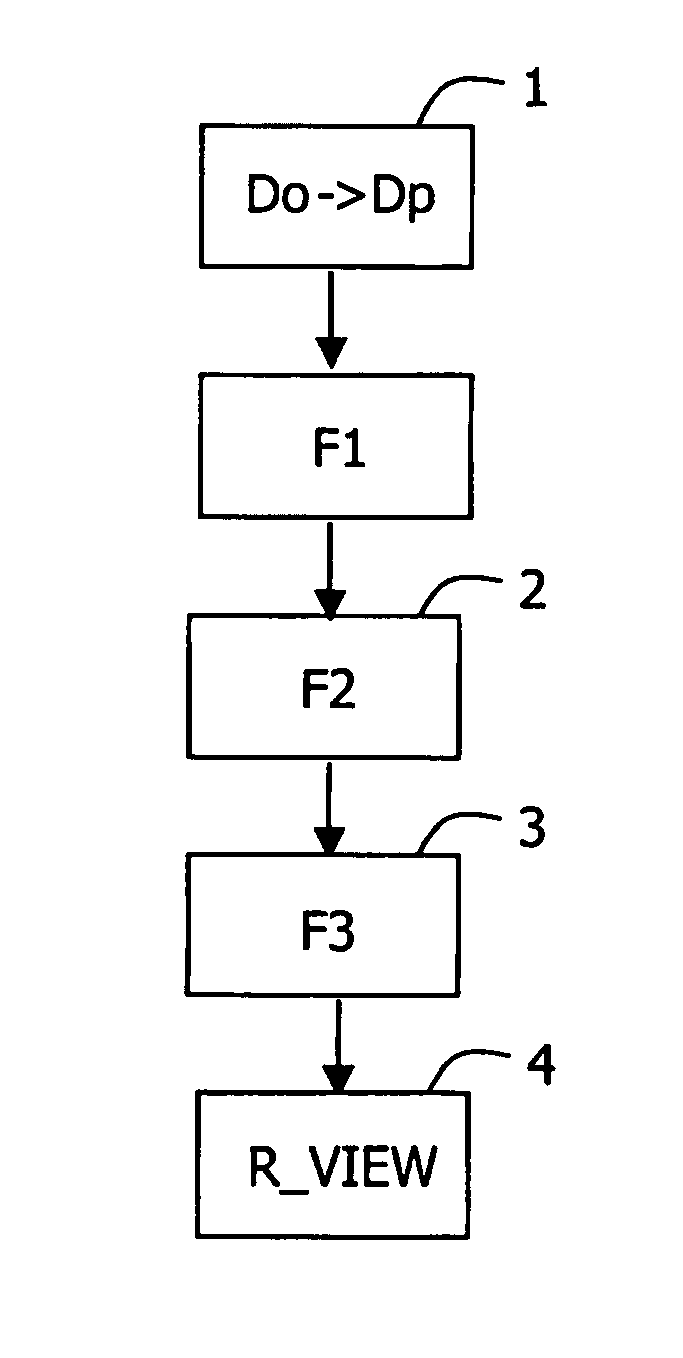
[0025] The present invention relates to a method for post-processing a digital video signal.

[0026] Such a method may be used within a video communication system for 3D video applications in MPEG4.

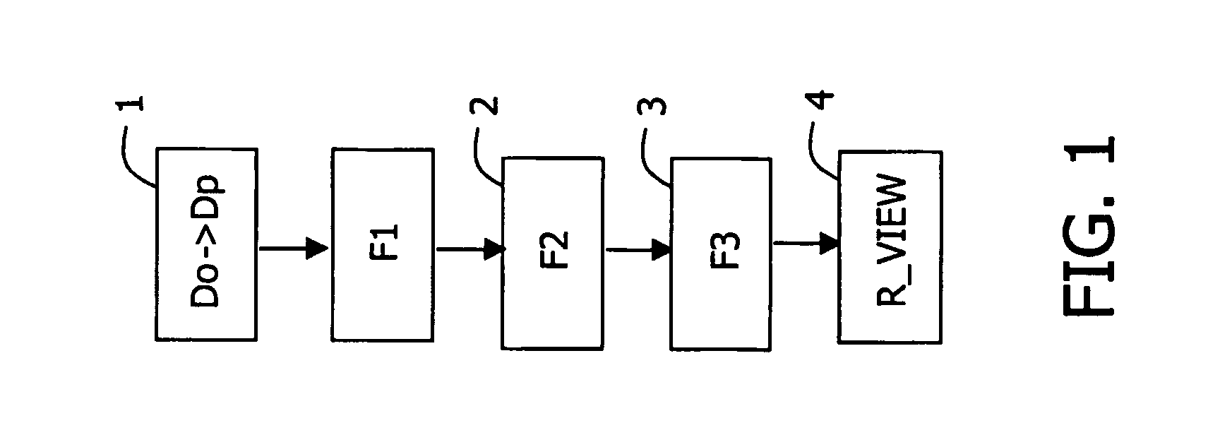
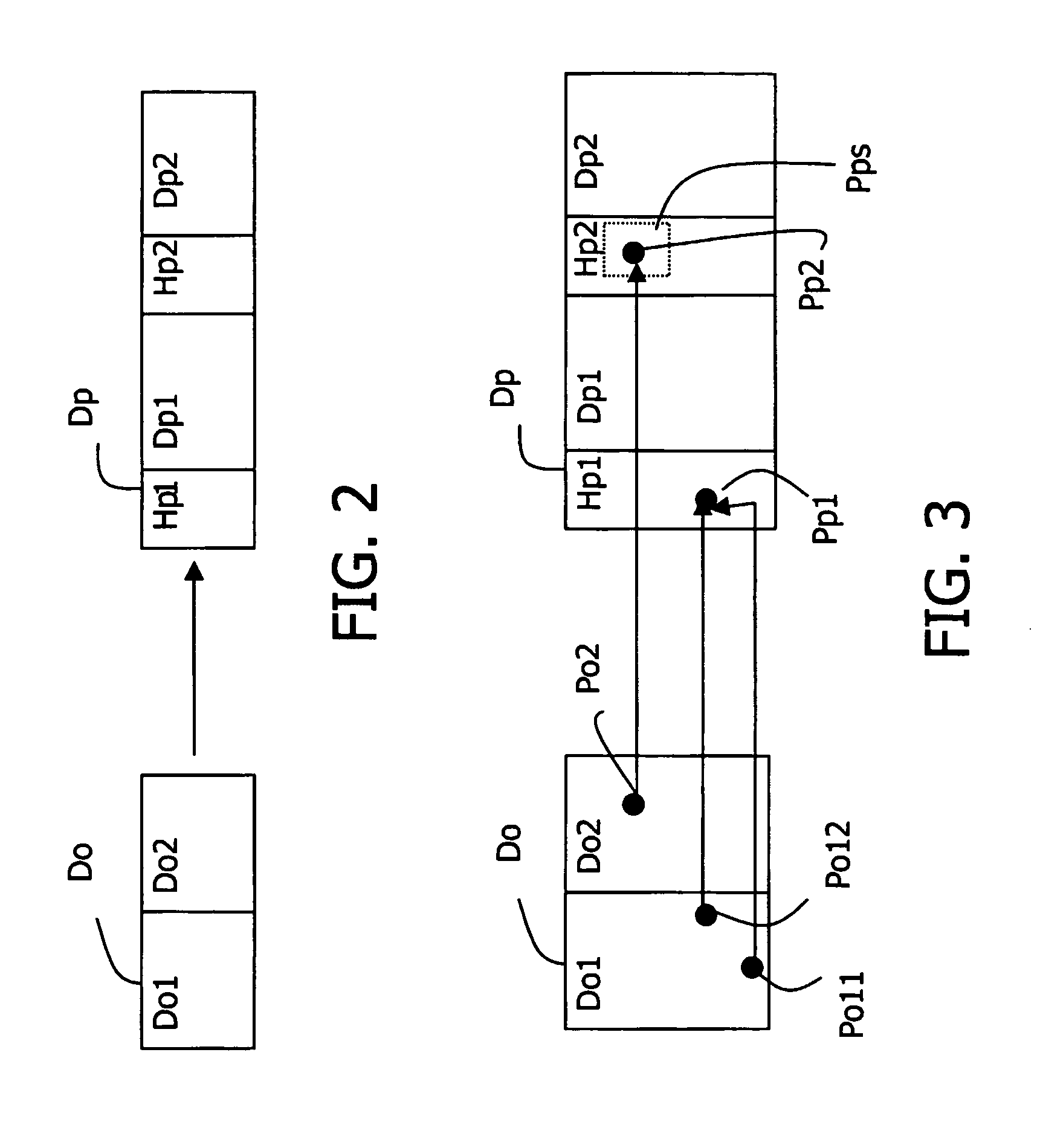
[0027] A 3D video signal comprises a plurality of points of view with different associated characteristics such as shape, texture, motion vectors, disparity map, depth map, colors, etc.

[0028] When a video signal is transmitted, it is encoded. During the encoding process, its different characteristics are encoded and especially the disparity and depth maps with a compression algorithm. This compression may lead to impaired disparity and depth maps with artifacts.

[0029] After transmission of the video signal, it is decoded, and then all its views are reconstructed during an algorithm that includes...


PUM


Abstract

The present invention relates to a method for post-processing a 3D digital video signal, said digital video signal having a plurality of views with associated disparity maps. The invention is characterized in that said method comprises a first step of generating a projected disparity map from an original disparity map, and a second step of filling holes within said projected disparity map, the first step comprising the sub-step of removing isolated projected pixels on said projected disparity map by filtering them.

Description

FIELD OF THE INVENTION [0001] The present invention relates to a method for post-processing a digital video signal, said digital video signal having a plurality of views with associated disparity maps. [0002] Such a method may be used in, for example, a video communication system for 3D video applications within MPEG standards. BACKGROUND OF THE INVENTION [0003] Most representations of 3D video signals called 3D scenes rely on depth maps and disparity maps. Generally, one starts from a set of images of a given 3D scene, corresponding to different points of view, each of them possibly coming with different associated characteristics such as a depth map and a texture. The depth map of a point of view is a grayscale image, each pixel of which contains the distance to a camera filming the scene. When one wants to generate a new point of view, also called more simply view, of the scene, it is possible to compute some areas of it, given another point of view, its depth map, the intrinsic ...

Claims


Application Information

Patent Timeline
IPC IPC(8): G06T15/40G06T7/00H04N13/122H04N13/128
CPCG06T7/0065G06T7/0075G06T2200/04H04N19/597H04N13/0011H04N13/0018H04N13/0022H04N13/0003G06T7/55G06T7/593H04N13/111H04N13/122H04N13/10H04N13/128H04N13/00
Inventor AUBERGER, STEPHANEPICARD, YANN
Owner KONINKLIJKE PHILIPS ELECTRONICS NV
Why Eureka
Try Eureka