
Image-taking apparatus

a technology of image-taking apparatus and led light, which is applied in the direction of exposure control, optical radiation measurement, instruments, etc., can solve the problems of inability to reach the subject the light emission power of leds is extremely small, and the auxiliary light for image-taking cannot reach the subject located far away from the camera

Active Publication Date: 2006-04-20
FUJIFILM CORP +1
View PDF11 Cites 8 Cited by
  • Summary
  • Abstract
  • Description
  • Claims
  • Application Information

AI Technical Summary

Benefits of technology

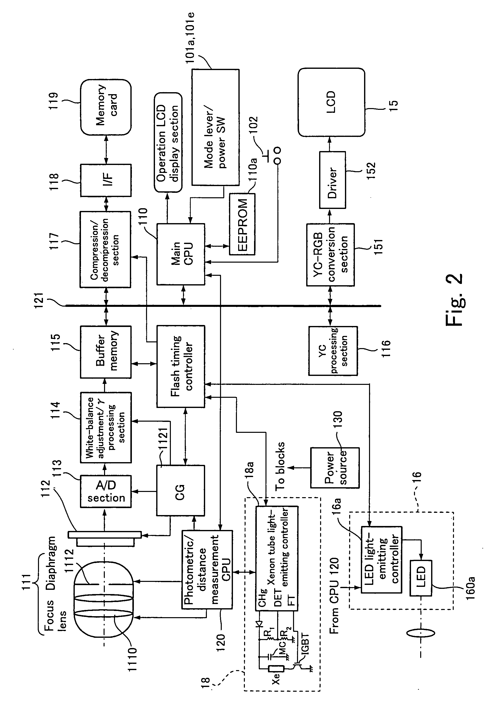
The present invention provides an image-taking apparatus with a light-emitting section that can quickly and efficiently emit light to a close subject. The apparatus includes a first light-emitting section with a xenon tube and a main capacitor, and a second light-emitting section with an LED. The apparatus also includes a full-charge sensor and a light-emission controlling section that causes the second light-emitting section to emit light when the main capacitor is not fully charged and the distance to the subject is shorter than a predetermined distance. This allows for quick and immediate light emission when the user wants to take an image immediately after the apparatus is turned on or after image taking with auxiliary light. The apparatus also includes a distance measuring section that detects the distance to the subject, and the light-emission controlling section causes the appropriate light-emitting section to emit light based on the distance to the subject. This allows for efficient use of the light-emitting section and saves power compared to conventional apparatus.

Problems solved by technology

However, the light emission power of LEDs is extremely small when compared to conventional xenon tubes.
Therefore, if a light-emitting unit employing an LED is incorporated in a camera, auxiliary light for image taking cannot reach a subject located far away from the camera, which is a problem.
Even if auxiliary light for image-taking emitted to a subject reaches the subject, the amount of such auxiliary light may not be enough, which leads to a shortage of the required amount of light.

Method used


Image

  • Image-taking apparatus
  • Image-taking apparatus
  • Image-taking apparatus

Examples


first embodiment

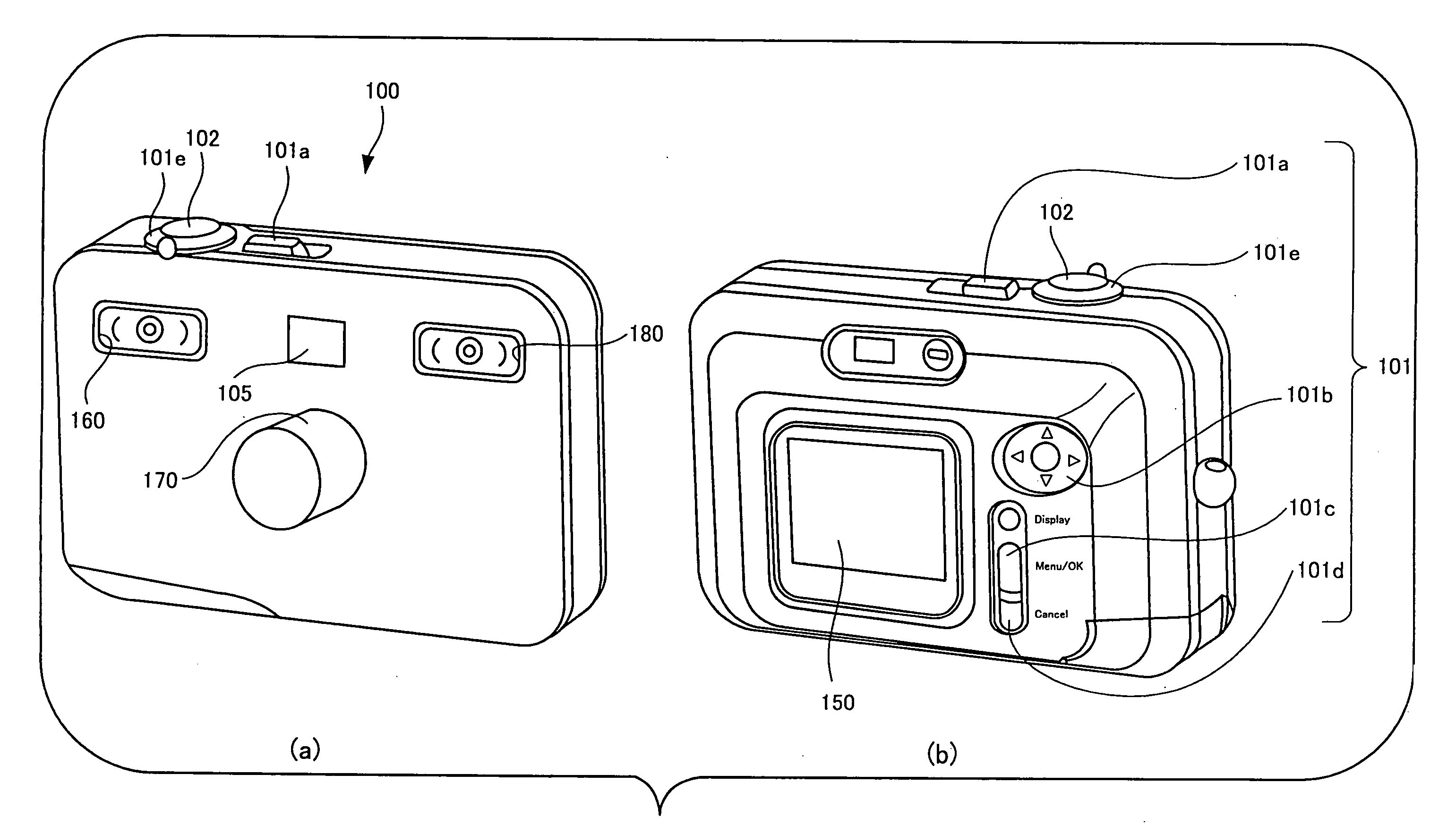
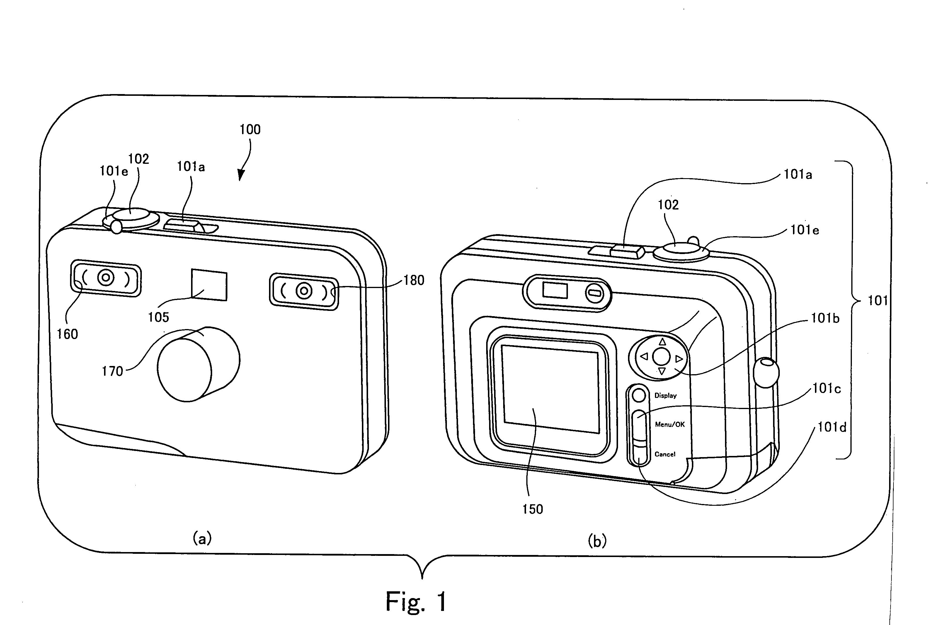
[0070]FIG. 1 shows a digital camera according to the image-taking apparatus of the present invention.

[0071]FIG. 1 is a perspective view of the digital camera according to the first embodiment of the present invention. Parts (a) and (b) of FIG. 1 show the front and the back of the digital camera as viewed from above, respectively.

[0072] As shown in Part (a) of FIG. 1, a digital camera 100 of the present embodiment has a lens barrel 170. The digital camera 100 is so configured as to guide a subject image through an image-taking lens incorporated in the lens barrel 170 and to form the image on a CCD solid-state imaging device disposed inside the digital camera 100. Also, the digital camera 100 is so configured as to generate image signals representing a through image and a taken image by means of the CCD solid-state imaging device which will be described later and to detect a distance to subject and subject brightness by performing TTL distance measurement and TTL metering based on th...

second embodiment

[0103] In view of such circumstances, the digital camera has been so modified as to emit auxiliary light for image taking from the second light-emitting section (LED) 16 only when a distance to subject measured by the photometric / distance measurement CPU 120 is shorter than a predetermined distance and when recharge of the main capacitor MC is not completed.

[0104] Description will be continued with reference to the flowchart shown in FIG. 5.

[0105] At step S3041, it is determined whether or not a distance allows image taking with the second light-emitting section (LED). When image taking requires auxiliary light, light is emitted from either the second light-emitting section or the first second light-emitting section depending on whether a distance to subject is short or long which is determined in comparison with a predetermined distance at step S3041.

[0106] More specifically, if it is determined that the distance is shorter than a predetermined distance (Yes) at step S3041, the ...

third embodiment

[0109]FIG. 6 is a flowchart showing a procedure of selecting a light-emitting section performed by a digital camera according to a

[0110] The flowchart shown in FIG. 6 is a flowchart improved by combining the selection according to a recharging condition of the main capacitor MC shown in FIG. 4 and the selection according to a measured distance value shown in FIG. 5.

[0111] If recharge of the main capacitor MC is not completed (No) at step S3041 and / or a distance to subject is shorter than a predetermined distance (Yes) at step S3042, the flow goes to step S3044 where light is emitted by the second light-emitting section. In contrast, if recharge of the main capacitor MC is completed (Yes) at step S3041 and a distance to subject is equal to or longer than the predetermined distance (No) at step S3042, the flow goes to step S3043 where light is emitted by the first light-emitting section.

[0112] Subsequently, at step S3045, an amount of light emitted from the xenon tube or the LED is ...


PUM


Abstract

The present invention provides an image-taking apparatus which includes: a first light-emitting section having a xenon tube and a main capacitor; and a second light-emitting section having an LED. When an image is to be taken with an auxiliary light emission immediately after power-on and immediately after previous image taking with a previous auxiliary light emission, recharge of the main capacitor is not completed yet. In such a case, the image-taking apparatus selects the second light-emitting section to emit auxiliary light from the LED.

Description

BACKGROUND OF THE INVENTION [0001] 1. Field of the Invention [0002] The present invention relates to an image-taking apparatus that generates image signals by forming a subject image on an imaging device through an image-taking optical system. [0003] 2. Description of the Related Art [0004] There has been proposed an image-taking apparatus employing both a halogen lamp and a xenon tube as a source for auxiliary light (see Japanese Patent Application Publication No. 9-90480 for example). [0005] In contrast, portable telephones equipped with a camera employ a power-thrifty LED as an auxiliary light source in recent years. Since the amount of light from such an LED is easy to control when compared to a xenon tube, techniques for controlling the amount of power emitted from an LED have been proposed and disclosed (see Japanese Patent Application Publication No. 2003-179808 for example). [0006] However, the light emission power of LEDs is extremely small when compared to conventional xen...

Claims


Application Information

Patent Timeline
Patent Type & Authority Applications(United States)
IPC IPC(8): G03B15/03G02B7/28G03B7/16G03B7/28G03B13/36G03B15/02G03B15/05
CPCG03B15/05G03B2215/0567G03B2215/0571
Inventor ENDO, HIROSHI
Owner FUJIFILM CORP
Learn More