DAL spinner

a technology of decorative spinners and dal spinners, which is applied in the direction of show cards, instruments, transportation and packaging, etc., can solve the problem of being able to read or discern

Inactive Publication Date: 2006-04-20
LAUDICK DAVID A
View PDF19 Cites 11 Cited by
  • Summary
  • Abstract
  • Description
  • Claims
  • Application Information

AI Technical Summary

Benefits of technology

[0009] The objectives of the DAL Spinner are: 1) to provide a spinner apparatus and method of making same such that the center detail or feature of the decorative ornament appears to be stationary in the plane of view of the observer at eye level from any direction while spinning; 2) to provide a spinner apparatus and method of making same such that the center feature of the decorative ornament can be a set of numbers such as a house number, a word or set of letters designating a person or company, a favorite player or drivers number, a university or pro-team logo or any of the standard holiday ornaments such as Christmas trees, stars, angels etc.; 3) to provide a spinner apparatus and method of making same such that the center feature is surrounded by concentric bands separated by fine cuts except where they remain attached at the top and bottom of each band and the top and bottom of the center feature; 4) to provide a spinner apparatus and method of making same such that the intermediate bands are progressively radially displaced about the vertical axis in small incremental angles from the plane of the outer band, the inner band and the center feature, giving the decorative ornament a three dimensional form; 5) to provide a spinner apparatus and method of making same such that the decorative ornament is formed economically by stamping, electrical discharge machining, laser or water jet cutting or chemical etching from a flat sheet of malleable metal that can be sanded providing light reflecting patterns and coated with a tinted transparent material; 6) to provide a spinner apparatus and method of making same such that the detail in the center section can be produced by cutting into the center pad with any of the conventional metal removing techniques or be added to a solid center panel with stickers, painting or printing; 7) to provide a spinner apparatus and method of making same such that it can be spun by wind blowing across its surface or by a decorative ornament display unit with an electric motor and a display light.

Problems solved by technology

The prior art shows a number of wind driven rotary devices, but none shown have the feature of being able to read or discern the identity of the center detail while the decorative ornament is spinning and none have the interesting moving light patterns generated by the DAL Spinner.

Method used


Image

  • DAL spinner
  • DAL spinner
  • DAL spinner

Examples


Embodiment Construction

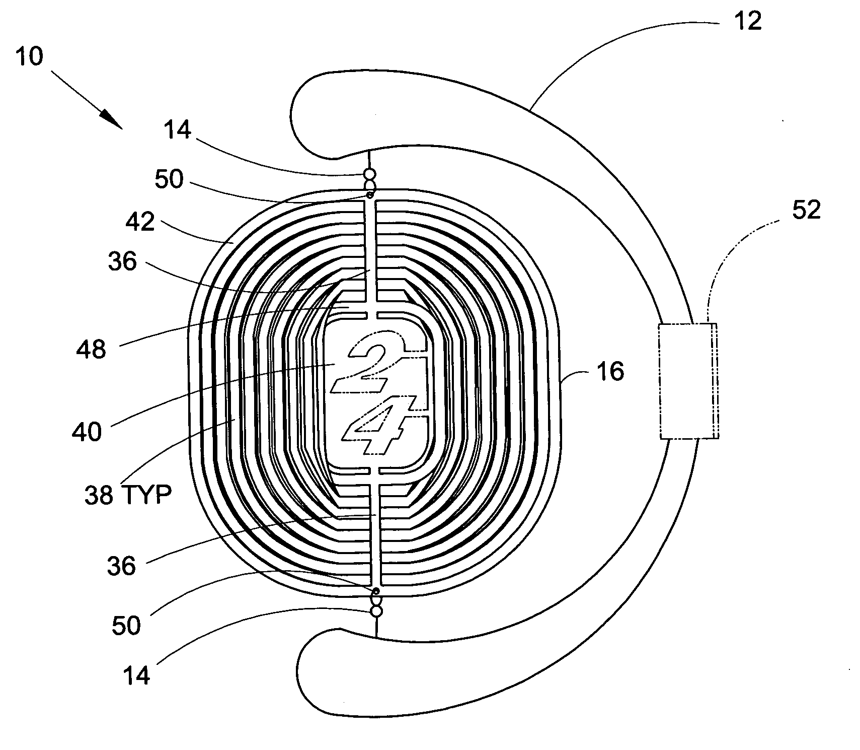
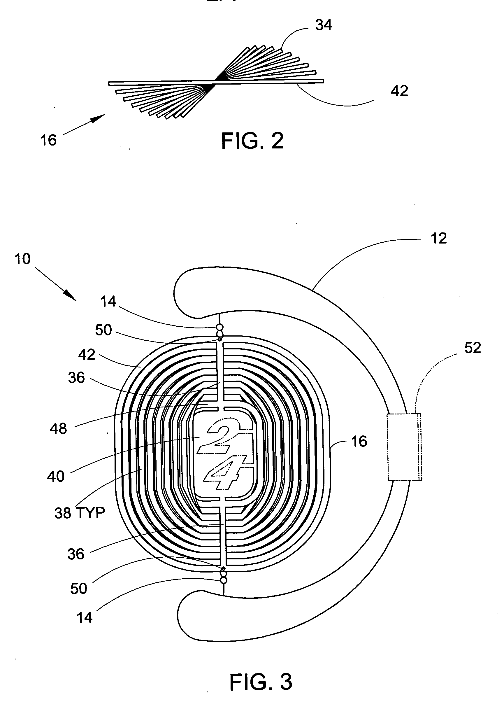
[0042] In order that the invention may be more fully understood, it will now be described by way of example with reference to the accompanying drawings which represent and illustrate both embodiments of DAL Spinner 10. DAL Spinner 10 can be utilized with passive “C” frame mount 12 and let the wind spin it or it can be used with motor driven, lighted decorative ornament display unit 18.

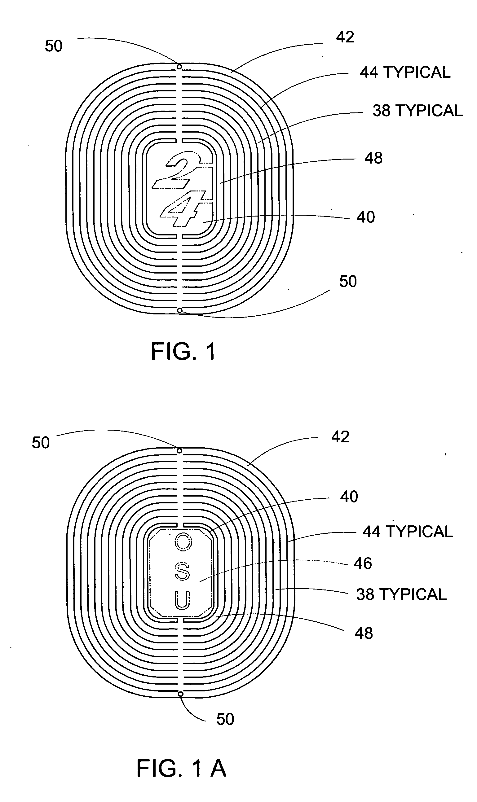
[0043] Turning to FIG. 1, decorative ornament 16 is shown in its stamped, etched, laser cut or machined flat state. Concentric bands 38 are divided by band separation cuts 44, the width of which are determined by the technology used for fabrication. The preferred embodiment utilizes a laser cut technique which generates a clearance between bands of approximately 0.005 inches. The space between inner band 48 and center feature 40 is approximately 0.25 inches which tends to highlight center feature 40. Separation cuts 44 stop approximately 0.125 inches from the top and bottom center of decorative orname...


PUM

PropertyMeasurementUnit
angleaaaaaaaaaa
transparentaaaaaaaaaa
curvature radiusaaaaaaaaaa

Abstract

This invention generally relates to decorative spinners. More specifically, this invention relates to a spinner apparatus rotated about its vertical axis, either by wind blowing across its face or in a second embodiment, spun by a motor drive unit. The spinner apparatus consists of a number or set of letters or other decorative symbol or logo on or in a pad centered between concentric bands of tinted transparent material coated metal which are connected at the top and bottom and progressively radially displaced about their vertical axis as they approach the inner band. When the device is spun either by the wind blowing it or by an electric motor, the numbers, letters or symbols stand out and appear to be stationary in the line of sight of the viewer and the bands progressively rotated off the plane of the outside band and the center detail provide an interesting wind catching and light reflecting three dimensional shape. When the spinning apparatus is lighted at night it takes on an electric glow appearance and the light appears to move either from the center outward or from the outside inward depending on the direction of rotation.

Description

BACKGROUND [0001] 1. Field of Invention [0002] This invention generally relates to decorative spinners. More specifically, this invention relates to a spinner apparatus rotated about its vertical axis, either by wind blowing across its face or in a second embodiment, spun by a motor drive unit. The spinner apparatus consists of a number or set of letters or other decorative symbol or logo on or in a pad centered between concentric bands of tinted transparent material coated metal which are connected at the top and bottom and progressively radially displaced about their vertical axis as they approach the inner track. When the device is spun either by the wind blowing it or by an electric motor, the numbers, letters or symbols stand out and appear to be stationary in the line of sight of the viewer and the bands progressively rotated off the plane of the outside track and the center detail provide an interesting wind catching and light reflecting three dimensional shape. When the spin...

Claims


Application Information

Patent Timeline
Patent Type & Authority Applications(United States)
IPC IPC(8): G09F17/00G09F1/00B23P9/00
CPCY10T428/12993G09F19/02
Inventor LAUDICK, DAVID A.
Owner LAUDICK DAVID A
Why Eureka
Try Eureka