Pilot unit, actuator system and method for producing said system

a technology of actuators and pilot units, applied in the direction of braking systems, vehicle sub-unit features, operating means/releasing devices of valves, etc., can solve the problems of increasing air consumption, difficult to produce bores, and prolonging the corresponding response time or actuation tim

Active Publication Date: 2021-03-02
WABCO EURO BVBA SPRL
View PDF22 Cites 1 Cited by
  • Summary
  • Abstract
  • Description
  • Claims
  • Application Information

AI Technical Summary

Benefits of technology

[0030]This allows an economic modular configuration using standardized starting materials for different valve systems or consumers, in which a yoke bracket is trimmed accordingly (in the transverse direction) and the necessary number of the several valves placed inside the yoke bracket. The pilot valves may in principle be formed with the same or largely similar parts for different functions. Thus 2 / 2-way blocking valves may be configured in standardized form. In other words, the 2 / 2-way blocking valves may be configured with the same valve parts to be used in the coil interior, e.g. armature, core (valve tube) and armature spring, in order e.g. also to allow optional configuration as a normally open or normally closed blocking valve. Mounting or assembly takes place by direct insertion in the common yoke bracket.
[0029]Furthermore, the pilot unit can be formed economically, in certain embodiments, as a modular system. The pilot valves may be, in certain embodiments, received with their parallel valve axes next to each other on a common yoke bracket, wherein they are e.g. placed next to each other between the two legs of the common yoke bracket. Thus only one common yoke bracket is required which e.g. may be formed as a curved plate of ferritic steel and allows the magnetic flux of each valve to be conducted outside the interior of the coil. Magnetic crossflows between the pilot valves may be suppressed e.g. by holes in the yoke bracket between the pilot valves.

Problems solved by technology

These bores are difficult to produce, either post-manufacture or e.g. in a plastic injection molding using oblique sliders in the injection molding tool.
In a relay valve for example, this extends the corresponding response time or actuation time and increases the air consumption.

Method used


Image

  • Pilot unit, actuator system and method for producing said system
  • Pilot unit, actuator system and method for producing said system
  • Pilot unit, actuator system and method for producing said system

Examples


Embodiment Construction

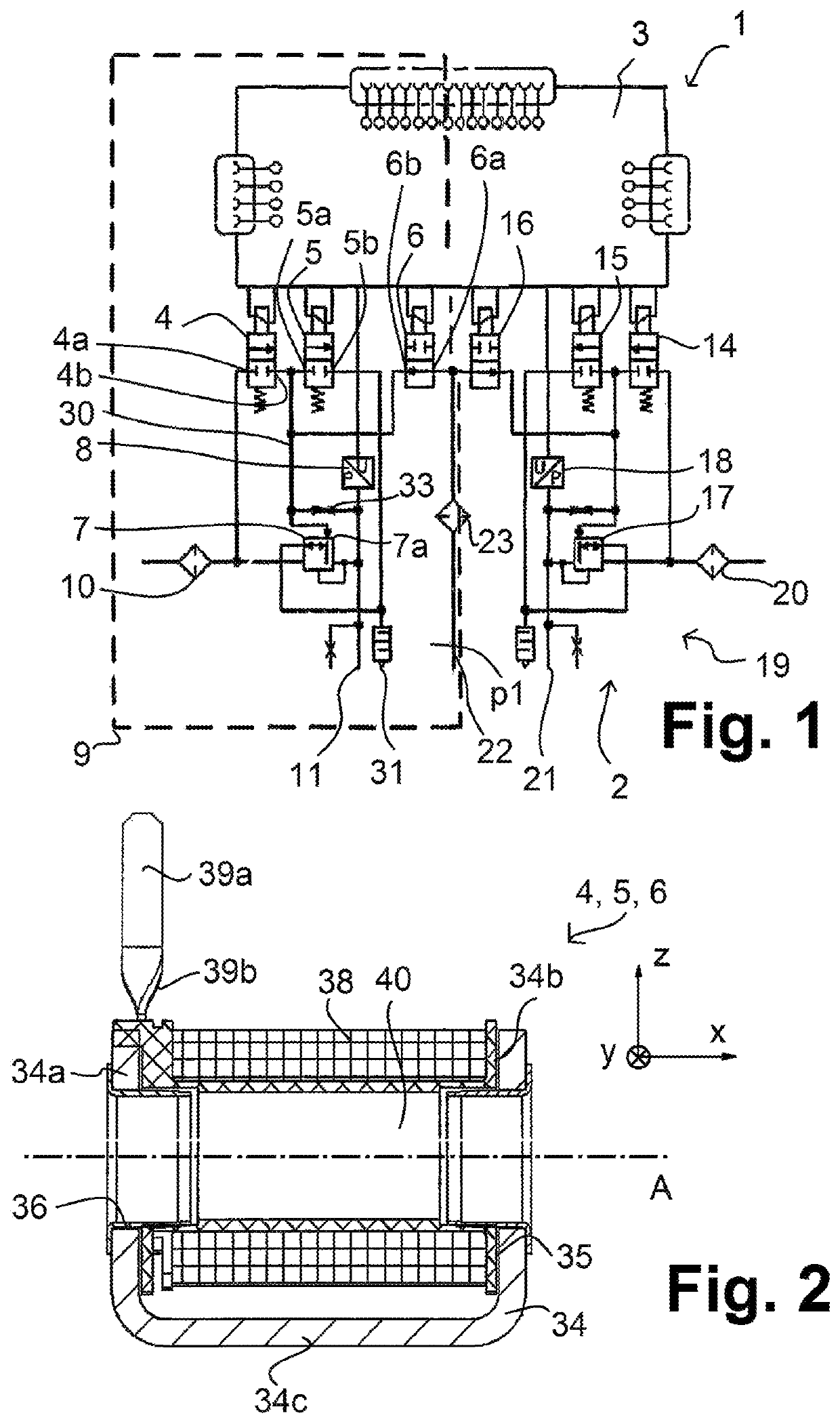
[0017]With reference to the specific embodiment of the figures, wherein like numerals generally indicate like parts throughout the several views, an electropneumatic pilot unit for an electropneumatic actuator system, such an electropneumatic actuator system and a method for its production, which can be formed at low cost is provided herein.

[0018]In certain embodiments, the electropneumatic actuator system provided herein is a dual-channel electropneumatic axle modulator for a brake system.

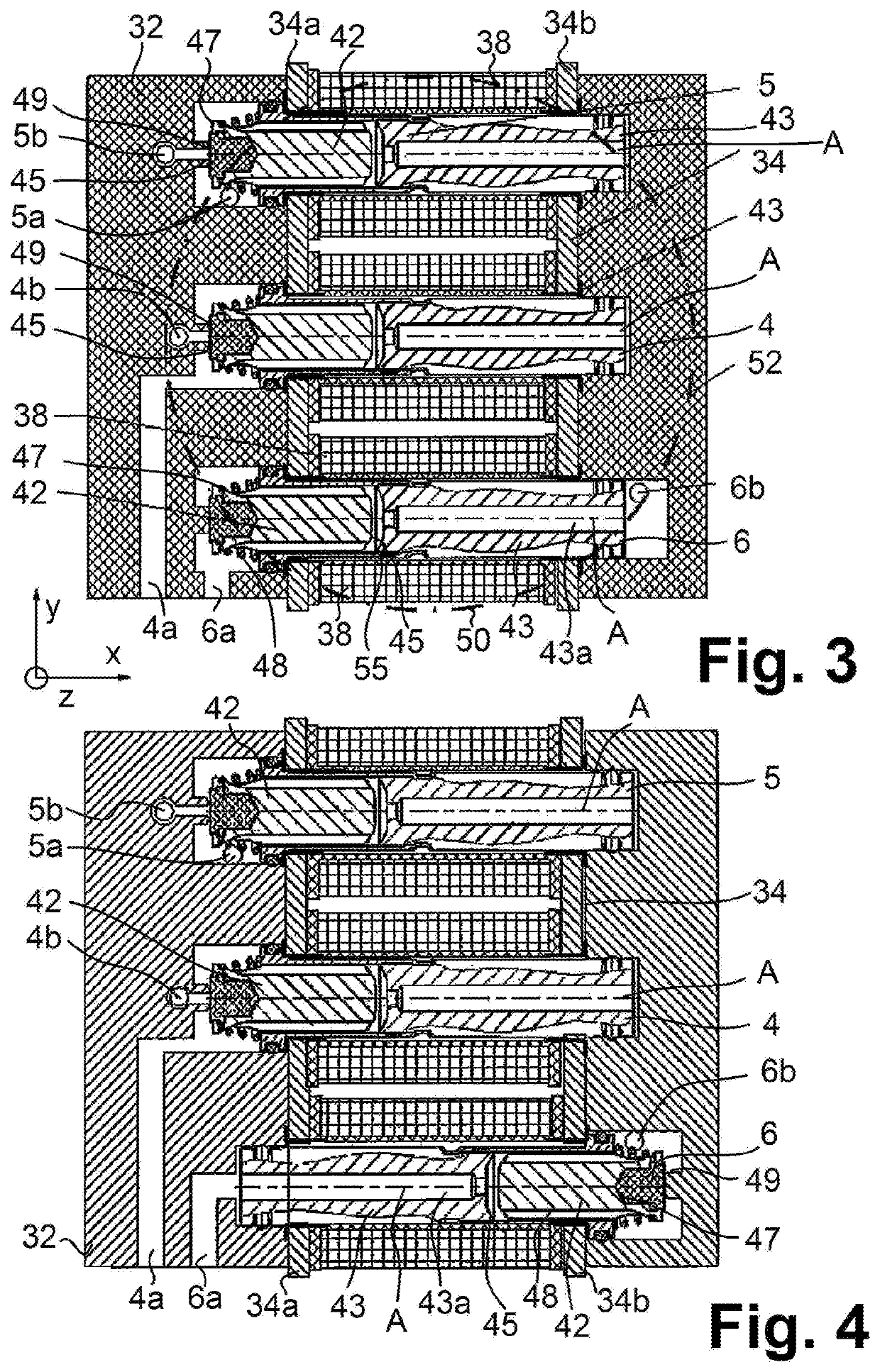
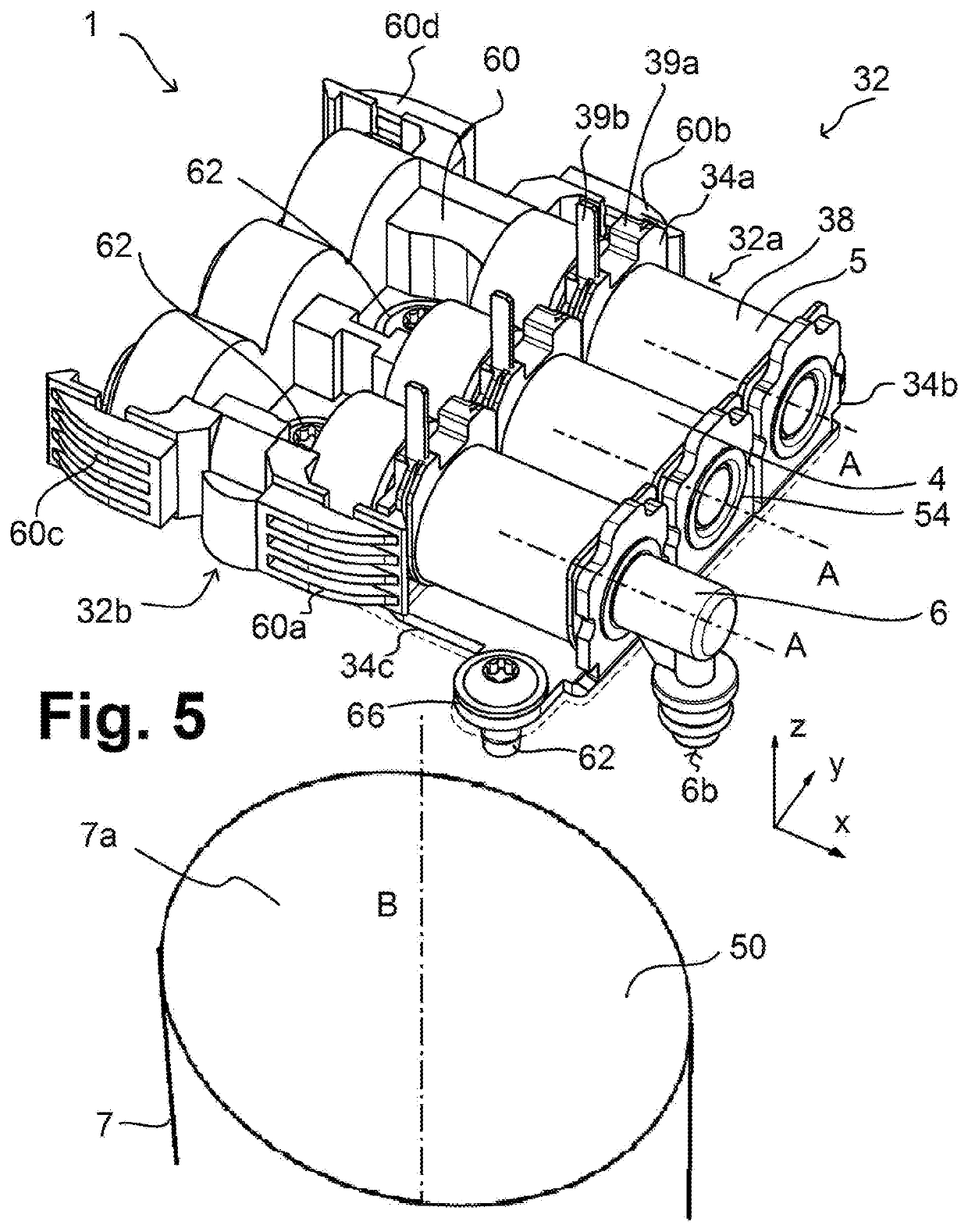
[0019]As described herein, the at least two or more pilot valves, in certain embodiments, electropneumatic pilot valves, are positioned next to each other such that their ports to be connected to the inlet port or pilot chamber of the consumer protrude towards a common underside. The pilot valves are therefore arranged next to each other, in various embodiments, parallel next to each other, in a sideways (lateral) direction perpendicular to their axial direction, wherein their ports protruding tow...


PUM


Abstract

An electropneumatic pilot unit for controlling a pneumatic consumer is provided herein. The pilot unit comprises at least two electromagnetic pilot valves. Each of the electromagnetic pilot valves comprises a coil for producing a magnetic flux along a valve axis, an armature which can be moved in the axial direction of the valve axis, a valve seat which can be closed and opened by the armature, and a pneumatic inlet port and a pneumatic outlet port. At least two of the pilot valves lie next to each other with parallel valve axes. Each pilot valve has a port which protrudes towards a common underside for connection to a pilot chamber of the consumer controlled by the pilot valves.

Description

CROSS-REFERENCE TO RELATED APPLICATIONS[0001]This application is the U.S. national stage of PCT / EP2017 / 000715, filed Jun. 20, 2017, which claims priority to German Patent Application No. 10 2016 009 944.5, filed Aug. 16, 2016, both of which are incorporated herein by reference in their entirety.FIELD OF THE DISCLOSURE[0002]The disclosure concerns a pilot unit and an actuator system with such a pilot unit, and a method for producing said system. The actuator system may in particular be a dual-channel electropneumatic or electrohydraulic axle modulator for a brake system of a vehicle.BACKGROUND[0003]Axle modulators in brake systems serve to control a brake pressure at the connected brake circuits of an axle. Axle modulators of EBS systems (electronic brake systems) generally control a system pressure of a compressed air storage reservoir via blocking valves (e.g., an inlet valve and an outlet valve) directly to a relay valve, which supplies a wheel brake with compressed air via a brak...

Claims


Application Information

Patent Timeline
Patent Type & Authority Patents(United States)
IPC IPC(8): F15B13/044B60T15/02B60T13/66B60T13/68B60T17/04B60T7/04B60T8/36F16K31/42B60T8/32
CPCB60T15/027B60T7/042B60T8/3605B60T8/3675B60T13/662B60T13/68B60T13/683B60T15/02B60T17/04F16K31/42B60T8/327B60T13/741B60Y2400/81
Inventor DIDWISZUS, LARSRUNGE, KARSTENSCHAPPLER, HARTMUTTEICHMANN, ANDREASTORHOFF, INGO
Owner WABCO EURO BVBA SPRL
Why Eureka
Try Eureka