
Electrical connection having a gold contact surface with discrete areas of hardness and fuel level sensor using the same

a technology of hardness and fuel level sensor, applied in the direction of connection contact member material, coupling device connection, instruments, etc., can solve the problems of short service life of soft gold, difficult durability, and relatively high pri

Active Publication Date: 2018-11-22
DELPHI TECH IP LTD
View PDF5 Cites 1 Cited by
  • Summary
  • Abstract
  • Description
  • Claims
  • Application Information

AI Technical Summary

Benefits of technology

The patent describes an electrical connection where two electrical conductors move relative to each other and provide a path for electrical communication. The surface of one of the conductors is coated with gold, which helps to ensure a stable connection between the two conductors. The patent also mentions that the coating can be used in a fuel level sensor. This design allows for better resistance and durability, and also makes the connection more economical.

Problems solved by technology

The sliding interface between the resistive circuit and the wiper assembly, and the harsh environment within which the fuel level sensor is located, present challenges in durability.
While this arrangement limits gold, which is relatively expensive, to the wiper assembly, soft gold may have a shorter service life than is desirable.
While the hard gold contact surface increases the durability of the wiper assembly, the service life of the silver-based resistive circuit may be shorter than is desirable due to the hard gold with which the silver-based resistive circuit interfaces.
While fuel level sensors which include a wiper assembly having a hard gold contact surface and a gold-based resistive circuit on the ceramic card provide a satisfactory service life, the cost of such an arrangement may be prohibitive to implement because of the increased amount of gold in the fuel level sensor.

Method used


Image

  • Electrical connection having a gold contact surface with discrete areas of hardness and fuel level sensor using the same
  • Electrical connection having a gold contact surface with discrete areas of hardness and fuel level sensor using the same
  • Electrical connection having a gold contact surface with discrete areas of hardness and fuel level sensor using the same

Examples


Embodiment Construction

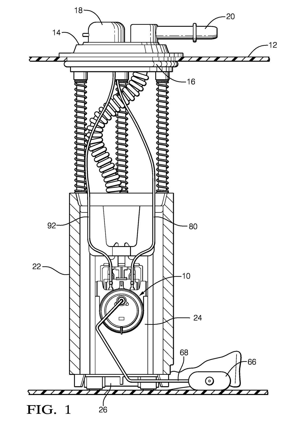
[0013]Referring to the drawings, and initially in particular FIG. 1 which illustrates an implementation of the present invention, a fuel level sensor 10 is shown for a fuel tank 12 (partially shown) of a vehicle (not shown). The fuel tank 12 includes a fuel pump module 14 therein with a removable cover 16 sealed to the top of fuel tank 12 with an electrical connector 18 and a fuel line outlet connector 20. Fuel pump module 14 includes a fuel reservoir 22 that contains an electrical fuel pump 24 with an inlet 26 and fuel level sensor 10 to indicate fuel level in the fuel tank 12.

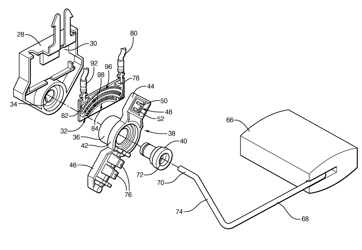
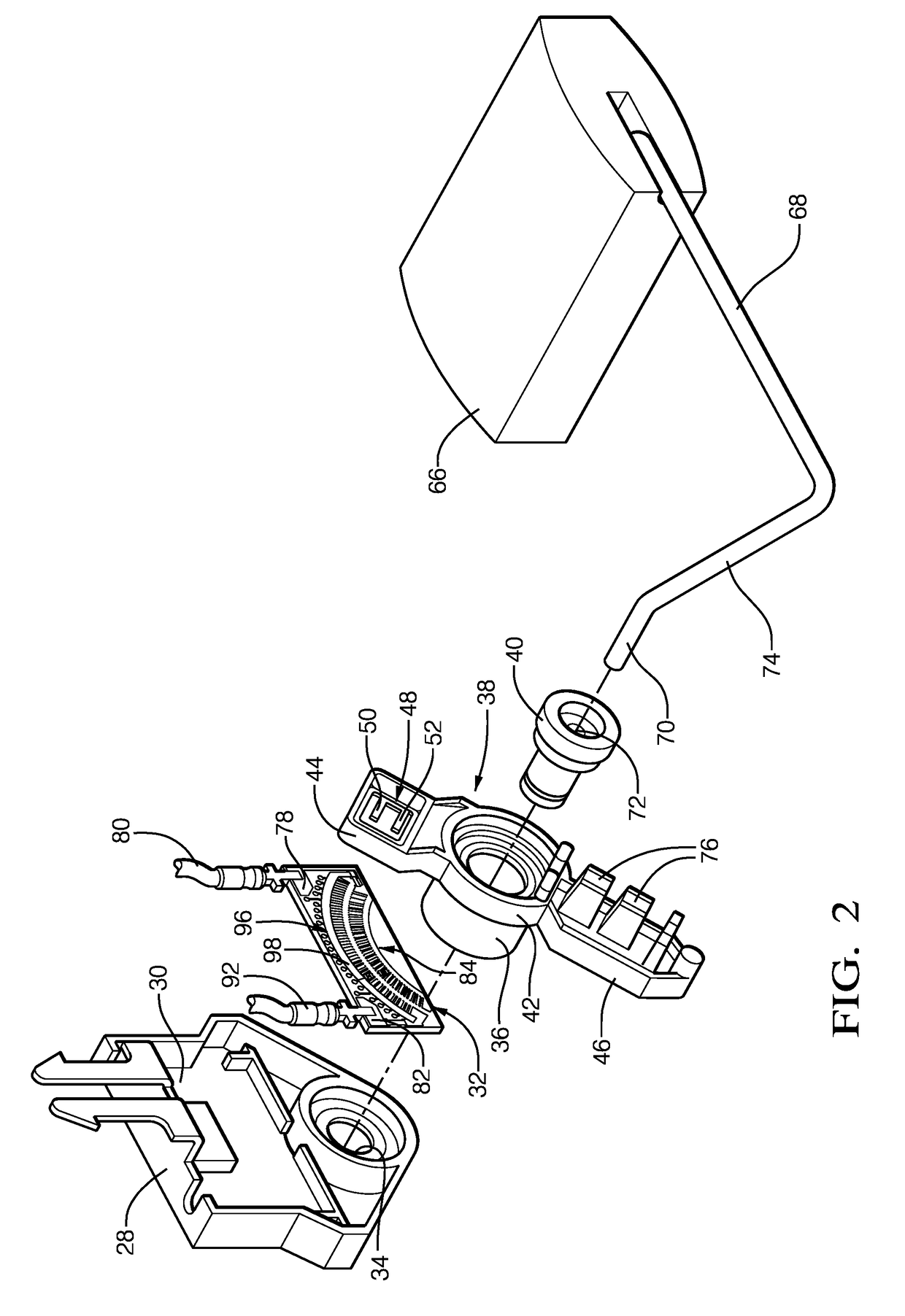
[0014]With continued reference to FIG. 1, but now with emphasis on FIGS. 2-4, fuel level sensor 10 includes a housing 28 having a recess 30 therein for carrying a resistor card 32. Housing 28 also has a recess or hole 34 therein for a hollow male portion 36 of a wiper assembly 38. Wiper assembly 38 is pivotally connected to housing 28 with the aid of a bushing 40, which extends through hollow male portion 36....


PUM


Abstract

An electrical connection includes a first electrical conductor assembly having a first electrical conductor with a first electrical conductor surface and a second electrical conductor assembly having a second electrical conductor with a second electrical conductor surface which is engaged with the first electrical conductor surface such that the second electrical conductor assembly and the first electrical conductor assembly reciprocate relative to each other along a path. The first electrical conductor surface and the second electrical conductor surface provide electrical communication between the first electrical conductor assembly and the second electrical conductor assembly along the path. The second electrical conductor surface has a first area of gold having a first magnitude of hardness which engages the first electrical conductor surface and also has a second area of gold having a second magnitude of hardness which is greater than the first magnitude of hardness.

Description

TECHNICAL FIELD OF INVENTION[0001]The present invention relates an electrical connection; more particularly to an electrical connection having a first electrical conductor with a first electrical conductor surface which mates with a second electrical conductor surface of a second electrical conductor; even more particularly to such an electrical connection where the second electrical conductor surface has a first area of gold having a first hardness and a second area of gold having a second hardness; and still even more particularly to a fuel level sensor which includes such an electrical connection.BACKGROUND OF INVENTION[0002]Fuel tanks which hold a volume of fuel, for example gasoline or diesel fuel, to be supplied to an internal combustion engine of a motor vehicle are known to include a fuel level sensor which generates a signal indicative of the fuel level within the fuel tank. The signal is provided to a fuel level gauge which delivers a visual display to an operator of the m...

Claims


Application Information

Patent Timeline
Patent Type & Authority Applications(United States)
IPC IPC(8): G01F23/36H01R35/04H01R12/71H01R4/62G01F23/76
CPCG01F23/363H01R35/04G01F23/76H01R4/62H01R12/714G01F23/36G01D5/165H01C10/32G01F23/32
Inventor PORRAS, LUIS M.CHAVEZ, ISAIMCHALE, MICHAEL JOSEPH
Owner DELPHI TECH IP LTD
Learn More