Method and apparatus for a low impedance anti-recirculation air moving inlet device

a technology of moving inlet device and low impedance, which is applied in the direction of electrical apparatus, electrical apparatus, electrical apparatus contruction details, etc., can solve the problems of reducing the flow rate that would otherwise be available, affecting the flow rate of air backward through the failed blower, and causing significant aerodynamic losses created by prior art designs. , to achieve the effect of low impedance air flow

Inactive Publication Date: 2006-04-20
IBM CORP
View PDF5 Cites 5 Cited by
  • Summary
  • Abstract
  • Description
  • Claims
  • Application Information

AI Technical Summary

Benefits of technology

[0007] In another embodiment, an apparatus includes an equipment enclosure having a plurality of air exchange interfaces for exchanging air between the interior and exterior of the enclosure and a plurality of blowers. Each blower resides at one of the air exchange interfaces and includes a blower housing having an inlet and an exhaust outlet. Each exhaust outlet shares a respective common plenum. An inlet recirculation apparatus is disposed at the inlet of each blower. Each inlet recirculation device includes a housing defined by a wall extending from a base having an aperture therethrough receptive to alignment with an inlet of the air moving device. A plurality of flaps each pivotally extending radially outwardly from a center pivot to another corresponding pivot disposed about a perimeter of the wall. The center pivot is coaxial with a center of the aperture, wherein each flap moves to an open position due to air pressure from the air moving device causing air to flow into the inlet wherein each flap pivotally rotates about the center pivot and the corresponding pivot. Each flap moves to a closed position when air pressure from the air moving device ceases wherein a space between contiguous flaps is eliminated when each flap pivotally rotates to the closed position about the center pivot and corresponding pivot to prevent reverse airflow through the air moving device.
[0008] A method for an anti-recirculation and low impedance air flow in air moving devices is further provided. The method includes disposing a housing at an inlet of the air moving device. The housing is defined by a wall extending from a base having an aperture therethrough receptive to alignment with the inlet of the air moving device. A plurality of flaps are disposed each pivotally extending radially outwardly from a center pivot to another corresponding pivot disposed about a perimeter of the wall. The center pivot is coaxial with a center of the aperture. Each flap moves to an open position due to air pressure from the air moving device causing air to flow into the inlet wherein each flap pivotally rotates about the center pivot and corresponding pivot. Each flap moves to a closed position when air pressure from the air moving device ceases wherein a space between contiguous flaps is eliminated when each flap pivotally rotates to the closed position about the center pivot and corresponding pivot to prevent reverse airflow through the air moving device.

Problems solved by technology

One problem with this type of parallel blower configuration is that when one blower fails, the pressure difference across the surviving blower pushes air backwards through the failed blower.
This reduces the delivered flow rate that would otherwise be available from the surviving blower.
However, the aerodynamic losses created by prior art designs are substantial and must be taken into consideration during system development, because they reduce airflow rate delivery in normal operation.
Therefore, although these prior art exhaust side systems prevent recirculation during a blower failure, they inadvertently produce large impedances during normal operation of the blower.

Method used


Image

  • Method and apparatus for a low impedance anti-recirculation air moving inlet device
  • Method and apparatus for a low impedance anti-recirculation air moving inlet device
  • Method and apparatus for a low impedance anti-recirculation air moving inlet device

Examples


Embodiment Construction

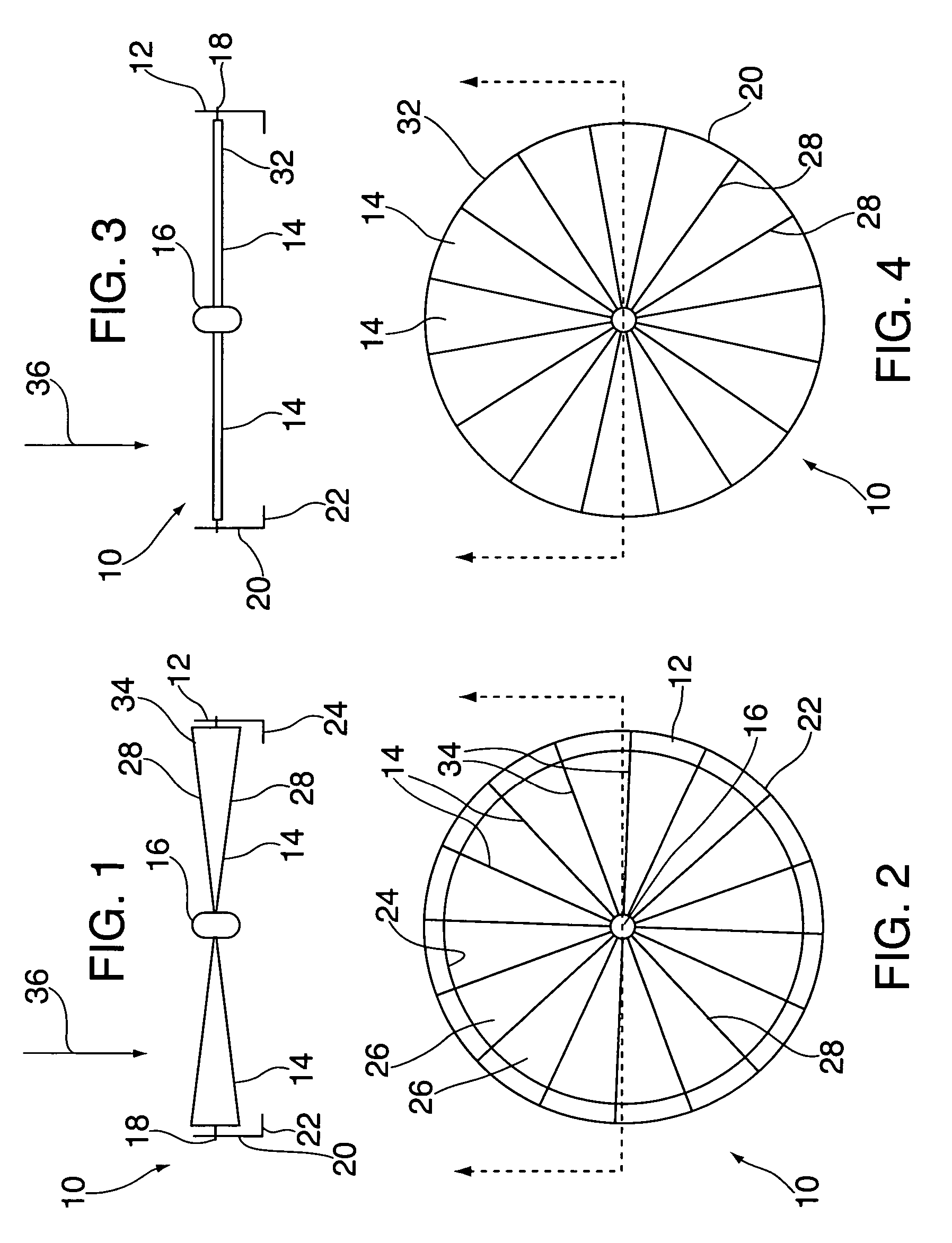
[0018] Referring now to FIGS. 1-4, an inlet recirculation device 10 is illustrated. Inlet recirculation device 10 includes a housing 12 and a plurality of flaps 14 pivotally extending radially outwardly from a center pivot 16 to an opposite pivot 18 extending from the housing 12.

[0019] Housing 12 includes a cylindrical wall 20 having a base 22 extending from one end. Base 22 defines an aperture 24 concentric with wall 20, as best seen with reference to FIG. 2, and is receptive to alignment with an inlet of an air moving device discussed more fully below. Although housing 20 and aperture 24 have been described as being round, other geometric shapes are envisioned and not limited to being round.

[0020] The plurality of flaps 14 each pivotally extend radially outwardly from center pivot 16 to an end pivot 18 at an opposite end. There is an end pivot 18 associated with each flap 14. End pivots are arranged around an inside perimeter defining wall 20 while center pivot 16 is substantial...


PUM


Abstract

An inlet recirculation apparatus for an air moving device includes a housing defined by a wall extending from a base. The base includes an aperture therethrough receptive to alignment with an inlet of the air moving device. A plurality of flaps each pivotally extends radially outwardly from a center pivot to another corresponding pivot disposed around a perimeter of the wall. The center pivot is coaxial with a center of the aperture. Each flap moves to an open position due to air pressure from the air moving device causing air to flow into the inlet wherein each flap pivotally rotates about the center pivot and corresponding pivot at the wall, and moves to a closed position when air pressure from the air moving device ceases wherein a space between contiguous flaps is eliminated when each flap pivotally rotates to the closed position about the center pivot and corresponding pivot at the wall to prevent reverse airflow through the air moving device.

Description

BACKGROUND OF INVENTION [0001] The present invention relates generally to cooling systems for electrical component enclosures, and in particular to a method and apparatus to prevent flow recirculation during failure of an air moving device used to cool electrical or other components within an enclosure. [0002] Electronic cooling systems designed for high availability or continuous operation often employ redundant air moving devices (e.g., fans or blowers) that are arranged in parallel. This arrangement is used to guard against catastrophic loss of cooling flow in the event of a single blower failure. One problem with this type of parallel blower configuration is that when one blower fails, the pressure difference across the surviving blower pushes air backwards through the failed blower. This reduces the delivered flow rate that would otherwise be available from the surviving blower. [0003] To prevent back flow, the normal practice is to add a flap-type device on the exhaust side of...

Claims


Application Information

Patent Timeline
Patent Type & Authority Applications(United States)
IPC IPC(8): H05K5/00
CPCH05K7/2019
Inventor CRUZ, ETHAN E.HOLAHAN, MAURICE F.SCHMIDT, ROGER R.
Owner IBM CORP
Why Eureka
Try Eureka