Gas removal from a centrifugal pump

a centrifugal pump and gas removal technology, applied in the direction of machines/engines, liquid fuel engines, therapy, etc., can solve the problems of invariably fatal interruption of the pumping action for the required length of time, early heart surgery difficult, side effects of heart/lung bypass surgery

Inactive Publication Date: 2006-04-20
HUBBARD LLOYD +1
View PDF11 Cites 14 Cited by
  • Summary
  • Abstract
  • Description
  • Claims
  • Application Information

AI Technical Summary

Problems solved by technology

This requirement made early heart surgery difficult as interrupting the heart's pumping action for the required length of time was invariably fatal.
Many of the bad side-effects of heart / lung bypass surgery are thought to result from prolonged blood contact with the various parts of the heart / lung machine.
The procedure is not without problems both for the surgeon and the patient.
The relatively high vacuum required to grasp the heart may result in blood blisters at the site of the suction cups.
Second, since the heart is pumping and the coronary arteries filled with blood, the surgeon must contend with spurting from the coronary artery during the grafting procedure.
Third, the cost of disposable devices is comparable to that required for conventional open-heart surgery;
Air is routinely entrained with the blood, and if not removed, could have fatal consequences for the patient.
However, the pore size of these membranes is restricted to a diameter that will allow cellular elements of the blood to pass through.
This requirement can compromise the membrane's ability to trap entrained air.

Method used


Image

  • Gas removal from a centrifugal pump
  • Gas removal from a centrifugal pump
  • Gas removal from a centrifugal pump

Examples


first embodiment

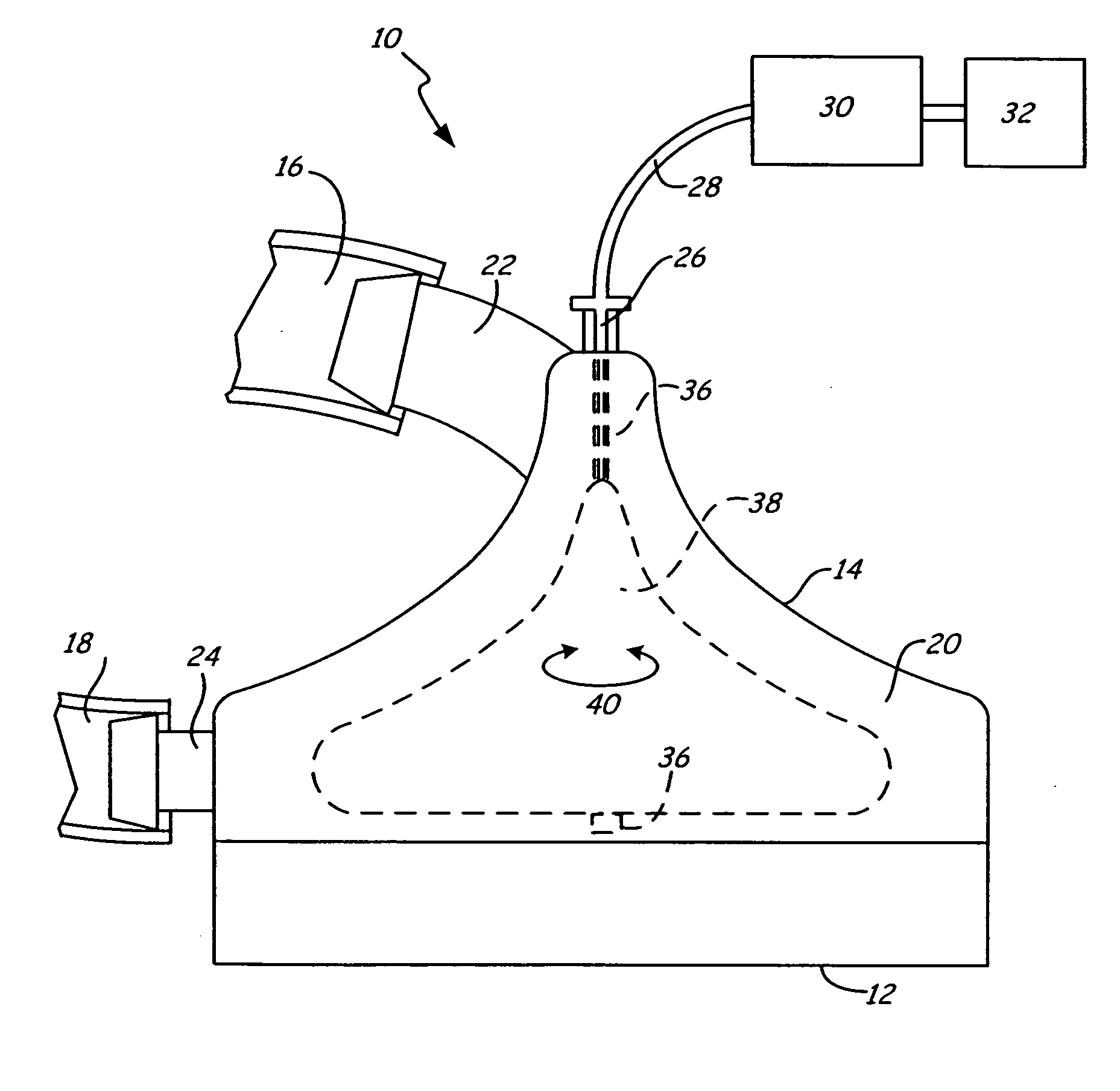
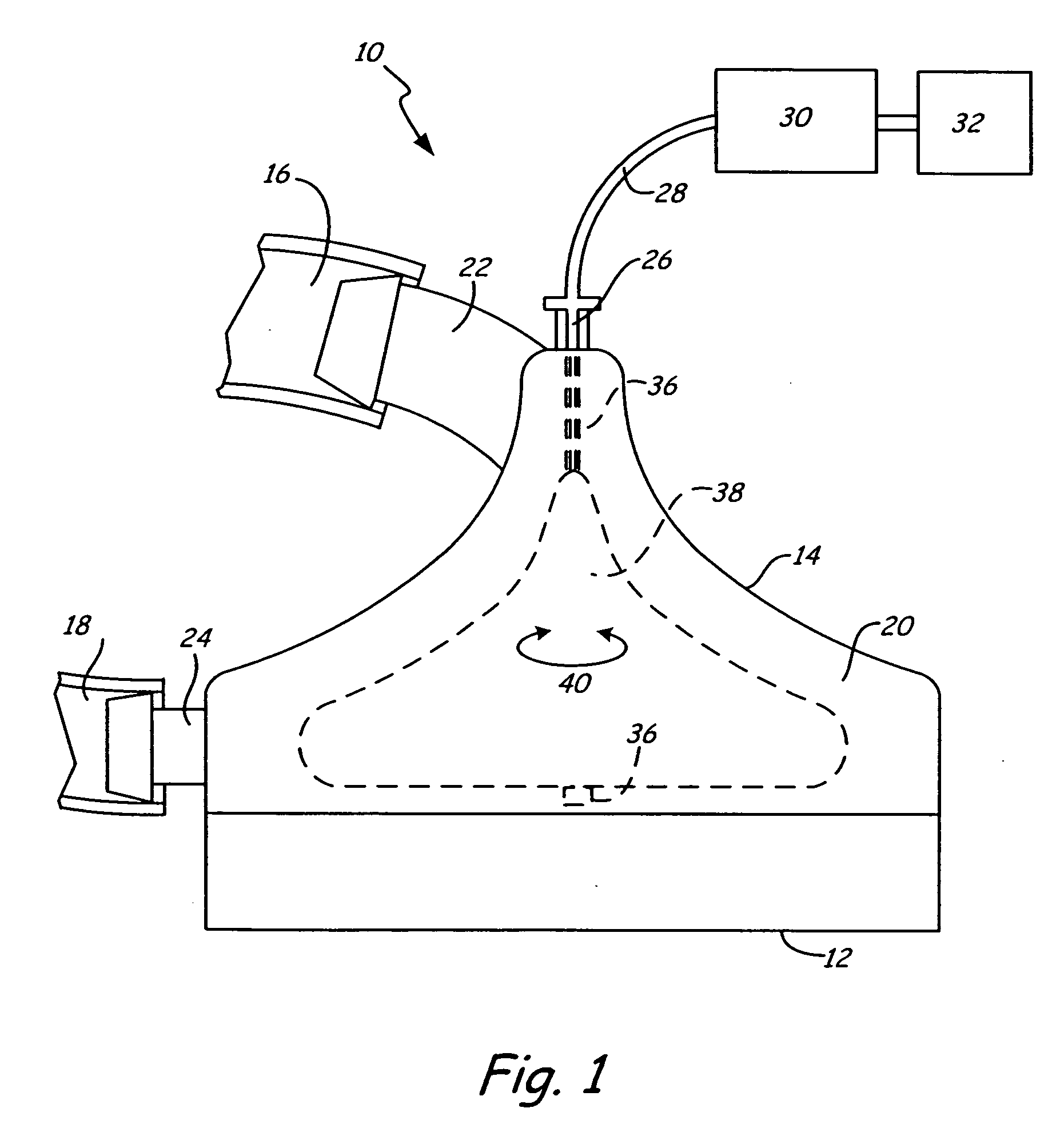
[0022]FIG. 2 is a first embodiment showing pump 14a. Pump 14a includes pump housing 20, pump chamber 20a, inlet 22, suction port 26, suction tubing 28 with sections 28a and 28b, bearing 34, rotating shaft 36, impeller 38, axis of rotation 40, sensor 42, shroud 44, collection space 46, vent 47, and vent inlet 48. FIG. 2 also shows reservoir 30, suction device 32, and accumulated gas 50.

[0023] Rotating shaft 36 is located along a midline within pump chamber 20a. Rotating shaft 36 is supported at its top end by bearing 34, and the bottom end of shaft 36 is connected to impeller 38. Shaft 36 and impeller 38 rotate around axis of rotation 40. Sensor 42 is shown located on shaft 36, however, it may be located on shroud 44 or any other structure that facilitates sensor 42 sensing the presence of gas in pump chamber 20a. Shroud 44 extends out from housing 20 and surrounds but does not contact shaft 36. Collection space 46 is formed between shaft 36 and shroud 44. Suction tubing 28 extends i...

second embodiment

[0026]FIG. 3 is a second embodiment showing pump 14b. Pump 14b includes pump housing 20, pump chamber 20a, inlet 22, suction port 26, suction tubing 28, bearing 34, impeller 38, axis of rotation 40, vent 47, hollow rotating shaft 52, and vent inlets 54. FIG. 3 also shows reservoir 30, suction device 32, and accumulated gas 50.

[0027] Here, vent 47 extends through shaft 52 such that vent 47 is in fluid communication with suction tubing 28. Suction port 26 is used to connect suction tubing 28 to housing 20. Suction port 26 may be, for example, a luer connector.

[0028] Vent inlets 54 are located along shaft 52 such that vent 47 is in fluid communication with pump chamber 20a. Vent inlets 54 are placed in a location where accumulated gas 50 accumulates along shaft 52. Though shown having multiple vents, one or more vents may be utilized with pump 14b.

[0029] In operation, as accumulated gas 50 accumulates, suction device 32 draws accumulated gas 50 through vent inlets 54, vent 47, and su...

third embodiment

[0030]FIG. 4 is a third embodiment showing pump 14c. Pump 14c includes pump housing 20, pump chamber 20a, inlet 22, suction port 26, suction tubing 28, bearing 34, impeller 38, axis of rotation 40, vent 47, hollow rotating shaft 52, and vent inlets 56. FIG. 4 also shows reservoir 30, suction device 32, and accumulated gas 50.

[0031] In this embodiment, vent inlets 56 are located on impeller 38. Thus, suction tubing 28 is in fluid communication with vent 47, which is in fluid communication with pump chamber 20a via vent inlets 56. Vent inlets 56 are placed at a location where accumulated gas 50 accumulates. Again, one or more vent inlets may be used in pump 14c.

[0032] In operation, as accumulated gas 50 accumulates within pump chamber 20a, suction device 32 draws gas 50 through vent inlets 56, vent 47, and suction tubing 28 and out of chamber 20a. Again, suction device 32 may be regulated by any of a number of ways including those described previously.


PUM


Abstract

A centrifugal pump includes a system that removes gas that accumulates along the axis of rotation of the shaft and/or impeller of the pump. One or more vent inlets are placed in the region where the gas accumulates and a suction device draws the accumulated gas through the vent inlets and a vent out of the centrifugal blood pump.

Description

BACKGROUND OF THE INVENTION [0001] The present invention relates to centrifugal blood pumps. In particular, the present invention relates to centrifugal blood pumps that remove accumulated gas. [0002] Delicate surgical procedures require that the site of surgery remain motionless. This requirement made early heart surgery difficult as interrupting the heart's pumping action for the required length of time was invariably fatal. [0003] Traditional heart surgery is carried out with the aid of a “heart / lung machine.” With the heart / lung machine in operation, the patient's heart is stopped while the surgeon performs the delicate surgery required to repair the ailing heart. The two fundamental parts of the heart / lung machine are a blood pump that takes the place of the arrested heart, and an oxygenator that replaces the patient's lungs during the surgical procedure. The heart / lung machine also includes filters, blood reservoirs, and plastic tubing as required to connect the several parts ...

Claims


Application Information

Patent Timeline
Patent Type & Authority Applications(United States)
IPC IPC(8): A61N1/362A61M60/10A61M60/232A61M60/408A61M60/515A61M60/538A61M60/818
CPCA61M1/101A61M1/3627Y10S415/90F04D9/003F04D9/006A61M60/818A61M60/113A61M60/408A61M60/232A61M60/538A61M60/10A61M60/515
Inventor HUBBARD, LLOYDCLAUSEN, EARL
Owner HUBBARD LLOYD
Why Eureka
Try Eureka