On-board message repeater for railroad train communications system

a message repeater and communications system technology, applied in repeater circuits, frequency-division multiplexes, instruments, etc., can solve the problems of slowing brake applications at railcars distant from the lead unit, un uniform braking force, and relatively high equipment costs

Active Publication Date: 2006-04-20
GE GLOBAL SOURCING LLC
View PDF9 Cites 85 Cited by
  • Summary
  • Abstract
  • Description
  • Claims
  • Application Information

AI Technical Summary

Problems solved by technology

Unfortunately, because the brake pipe runs for several thousand yards through the train, the emergency brake application does not occur instantaneously along the entire length of the brake pipe.
Thus the braking forces are not uniformly applied at each railcar to stop the train.
As can be appreciated, brake pipe venting at only the lead unit in a conventional train requires propagation of the brake pipe pressure reduction along the length of the train, thus slowing brake applications at railcars distant from the lead unit.
Although high-power, robust transceivers may be capable of successfully transmitting the signal to the receiving unit under certain operating conditions, such equipment can be relatively expensive.
Further, in some operating scenarios even a high-power transceiver cannot successfully effect communications, such as when a long train travels a curved track segment adjacent a natural obstruction such as a mountain, where the communications path between the lead unit and one or more remote units is obstructed by the mountain.
Also, as the train passes through a tunnel certain transceivers may be unable to communicate with other transceivers aboard the locomotives.

Method used


Image

  • On-board message repeater for railroad train communications system
  • On-board message repeater for railroad train communications system
  • On-board message repeater for railroad train communications system

Examples


Embodiment Construction

[0056] Before describing in detail the particular method and apparatus for a priority message protocol for an on-board message repeater system in accordance with the present invention, it should be observed that the present invention resides primarily in a novel combination of hardware and software elements related to said method and apparatus. Accordingly, the hardware and software elements have been represented by conventional elements in the drawings, showing only those specific details that are pertinent to the present invention, so as not to obscure the disclosure with structural details that will be readily apparent to those skilled in the art having the benefit of the description herein.

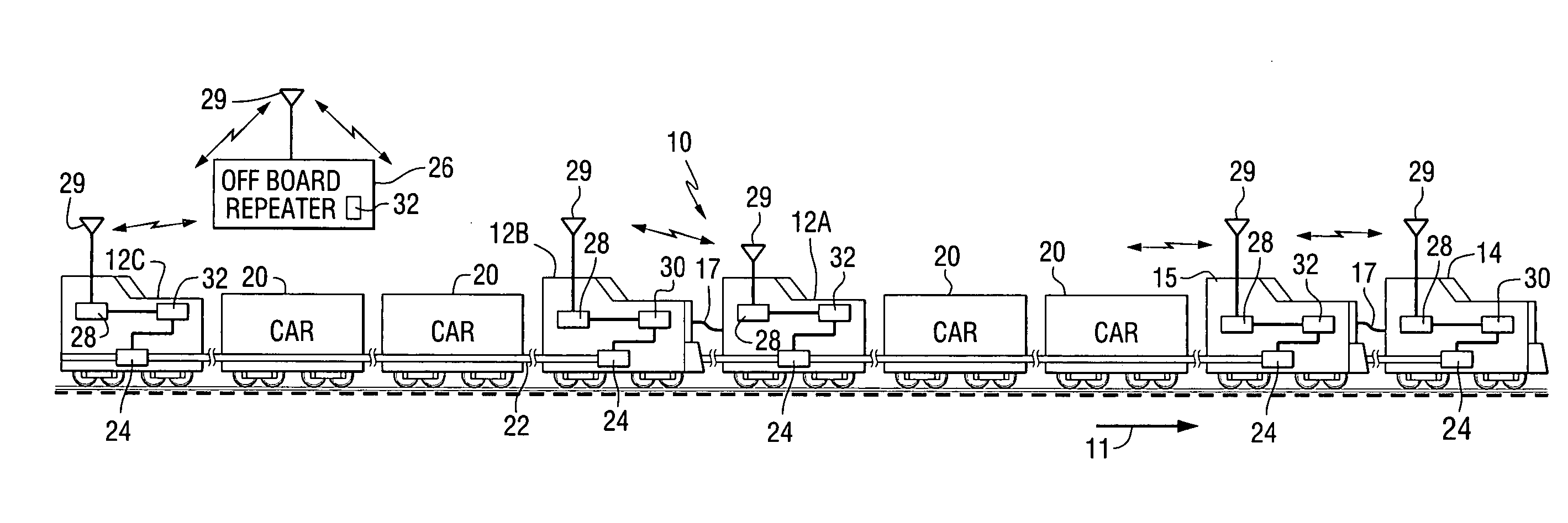
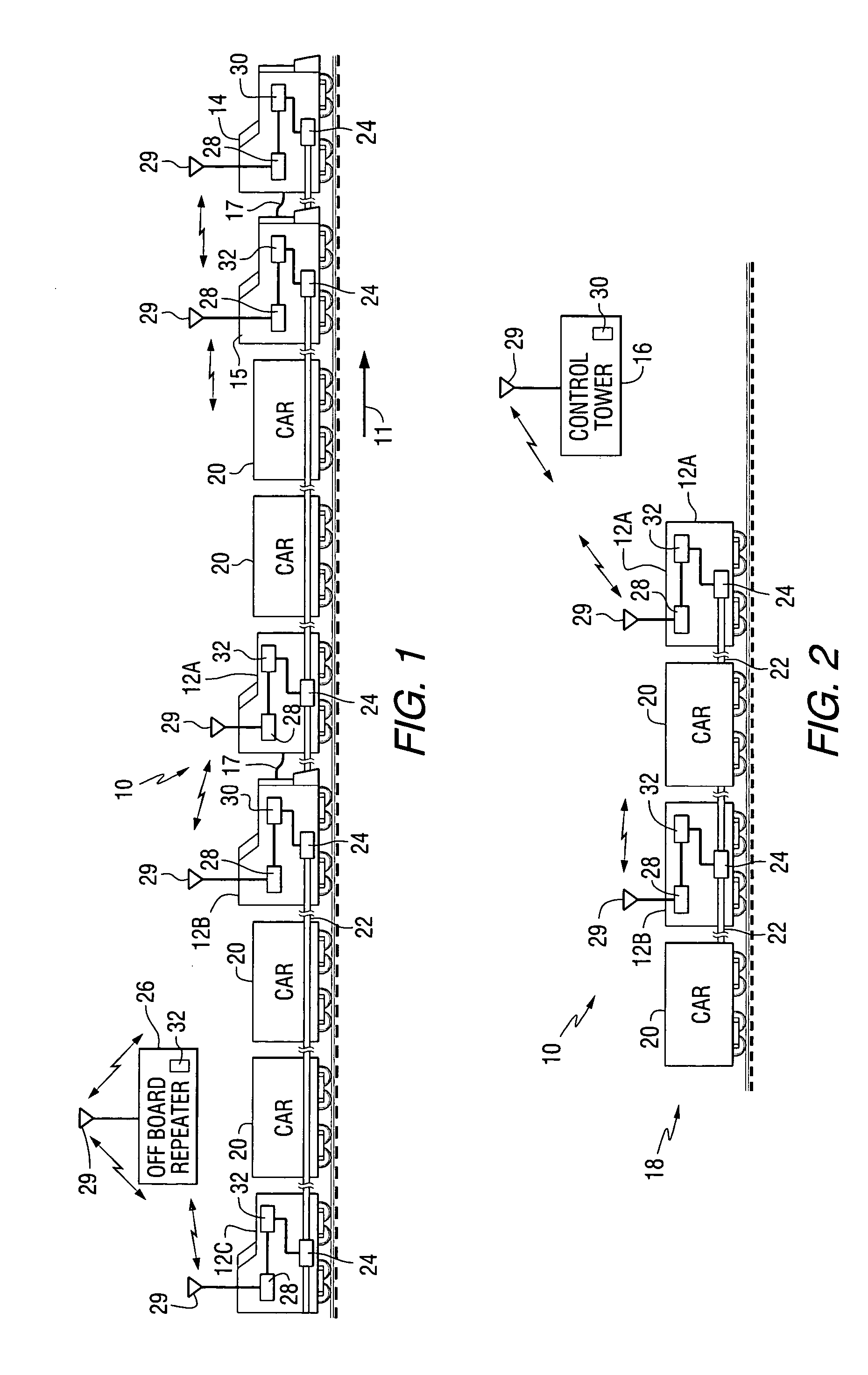
[0057] According to a preferred embodiment of the present invention, comprising a priority message protocol for an on-board message repeater system in a distributed power train, such as the distributed power train 10 of FIG. 1, messages transmitted from the lead unit 14 leapfrog down the trai...


PUM


Abstract

A distributed power train (10) communications system for sending and receiving signals between a lead locomotive (14) and remote locomotives (12A / 12B / 12C) in the train (10). A lead (14) initiated message is received by at least the remote locomotive (12A / 12B) nearest to the lead unit (14). The receiving remote unit (12A / 12B) retransmits the message for receiving by the next remote unit (12C) in the train. Thus the message leapfrogs down the train from the lead unit (14) to the remote units (12A / 12B / 12C). When the last remote unit (the nth remote unit) (12C) receives the message, the last remote (12C) transmits a status or other response message to the lead unit's message. The status message is received at the (n-1)th remote unit (12A / 12B), which appends its status message and transmits the combined status messages toward the lead unit (14). Each successive remote unit receives the status messages of the other remote units and appends its status message, until the concatenated status message reaches the lead unit (14).

Description

[0001] This patent application claims the benefit of U.S. Provisional Patent Application No. 60 / 565,591 filed on Apr. 26, 2004.FIELD OF THE INVENTION [0002] This invention relates generally to railroad train communications systems and particularly to an on-board message repeater for railroad train communications systems for use with a distributed power train comprising a lead locomotive and one or more remote locomotives. BACKGROUND OF THE INVENTION [0003] Distributed power railroad train operation supplies motive power and braking action from a lead locomotive (or lead unit) and one or more remote locomotives (or remote units) spaced apart from the lead unit in a train. In one configuration, a distributed power train comprises a lead locomotive at a head end of the train, a remote locomotive at an end of train (EOT) position and one or more mid-train locomotives disposed between the head end and the end of train. Distributed train operation may be preferable for long train consists...

Claims


Application Information

Patent Timeline
Patent Type & Authority Applications(United States)
IPC IPC(8): G05D1/00B61L15/00
CPCB61L15/0027B61L27/0038H04B7/2606H04B7/0608H04B7/0802B61L27/20
Inventor SMITH, EUGENE A. JR.PELTZ, DAVID MICHAELPALANTI, ROBERT C.
Owner GE GLOBAL SOURCING LLC
Why Eureka
Try Eureka