Method and system for placing components by means of at least one component placement unit

a technology of component placement and component unit, which is applied in the direction of speed measurement using gyroscopic effects, gyroscope/turn-sensitive devices, transmission, etc., can solve the problem of relatively low capacity, i.e., the number of components to be placed per unit time, and achieve the effect of increasing the capacity of the component placement uni

a technology of component placement and component unit, which is applied in the direction of speed measurement using gyroscopic effects, gyroscope/turn-sensitive devices, transmission, etc., can solve the problem of relatively low capacity, i.e., the number of components to be placed per unit time, and achieve the effect of increasing the capacity of the component placement uni

US20060085975A1Inactive Publication Date: 2006-04-27ASSEMBLEON NV

Image

  • Method and system for placing components by means of at least one component placement unit
  • Method and system for placing components by means of at least one component placement unit
  • Method and system for placing components by means of at least one component placement unit

Examples


Embodiment Construction

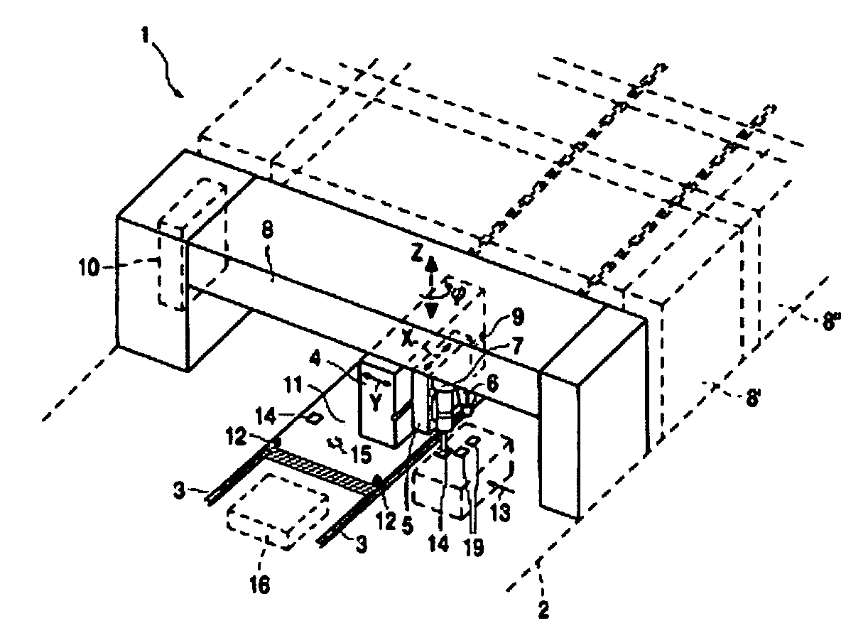
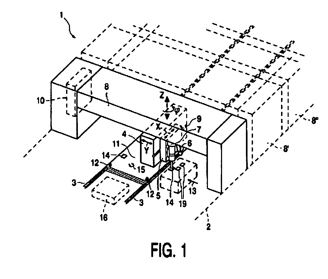
[0024] The present invention provides a method and a system of placing components. For example, FIG. 1 shows a system 1 according to the invention comprising a frame 2, transport rails 3 supported by the frame 2 and a device 4 which is movable above the transport rails 3, to which a component placement unit 5 is connected. The component placement unit 5 is provided with a camera 6 and a nozzle 7. The device 4 can be moved, by means that are known per se, in the direction indicated by the arrow Y and in the opposite direction via a guide (not shown) that is mounted on a bridge 8. The component placement unit 5 is movable in the direction indicated by the arrow X over a guide 9 that is present on the device 4. The nozzle 7 is furthermore movable in the direction indicated by the arrow Z and in the opposite direction. The system 1 also comprises a processor 10.

[0025] A substrate 11 is moved in the direction indicated by the arrow X and in the opposite direction to a position located n...


PUM

PropertyMeasurementUnit
distanceaaaaaaaaaa
total distanceaaaaaaaaaa
average distanceaaaaaaaaaa

Abstract

Provided is a method and system for placing components by means of at least one component placement unit wherein the component placement unit is moved over a distance between a component pickup position and a component placement position located on a substrate. In addition, a total distance to be covered by the component placement unit is calculated for the number of components to be placed, wherein the number of components to be placed is determined beforehand. This total distance value is subsequently compared with a reference value. If the total distance value is greater than the reference value, the substrate to be provided with the components is rotated with respect to the component pickup position about an axis that extends perpendicularly to the substrate.

Description

CLAIM OF PRIORITY [0001] This application claims priority from European Patent Application No. 04101060.4, filed Mar. 16, 2004, the entire teachings of which are incorporated by reference. FIELD OF THE INVENTION [0002] The present invention relates to methods of placing components by component placement units. More specifically, the invention relates to a method for placing components by means of at least one component placement unit, where the component placement unit can be moved over a distance between a component pickup position and a component placement position located on a substrate. [0003] The invention further relates to a system comprising at least one component placement unit for placing components, where the component placement unit can be moved over a distance between a component pickup position and a component placement position located on a substrate. BACKGROUND OF THE INVENTION [0004] In general component positioning methods and systems, which are known from WO-A-98 / ...

Claims


Application Information

Patent Timeline
27 Apr 2006
Publication
US20060085975A1
IPC
B23P19/00; H05K13/04; H05K13/00; H05K13/02; H05K13/08
CPC
H05K13/08; H05K13/0413; Y10T29/49131; Y10T29/53178; Y10T29/49133; Y10T29/4913; H05K13/0853; H04B1/52
Inventors
VAN DER GRAAF, SEBASTIAAN EDWARD