Method and device for manufacturing integrally bladed rotors

a technology of integral blades and rotors, applied in the direction of manufacturing tools, electrical-based machining electrodes, vibration holders of electrodes, etc., can solve the problems of difficult manufacturing of recesses, uneconomical cutting, etc., and achieve the effect of efficient manufacturing of integral bladed rotors

Active Publication Date: 2006-04-27
MTU AERO ENGINES GMBH
View PDF1 Cites 15 Cited by
  • Summary
  • Abstract
  • Description
  • Claims
  • Application Information

AI Technical Summary

Benefits of technology

[0007] According to the present invention, it is provided that the recesses serving as blade gaps are produced by electrochemical machining of the basic rotor body. To do so, according to the present invention a plurality of working electrodes are moved simultaneously into the basic rotor body to produce a plurality of recesses serving as blade gaps. For this purpose, a relative motion is established between the working electrodes and the basic rotor body, the relative motion having a translational motion component and a rotational motion component, which at least partially overlap. Due to the overlap of the translational motion component and the rotational motion component in producing the recesses serving as blade gaps, helical contour-shaped recesses are produced, which are already adapted to the desired final contour of the blades of the integrally bladed rotor. This makes it possible to efficiently manufacture integrally bladed rotors by electrochemical machining.

Problems solved by technology

However, cutting is problematic and uneconomical, in particular for difficult-to-cut materials.
However, wire erosion and water jet cutting have the disadvantage that only straight cutting surfaces are possible, so that it is not possible to manufacture the recesses, i.e., the unmachined blades, by following the contours.

Method used


Image

  • Method and device for manufacturing integrally bladed rotors
  • Method and device for manufacturing integrally bladed rotors
  • Method and device for manufacturing integrally bladed rotors

Examples


Embodiment Construction

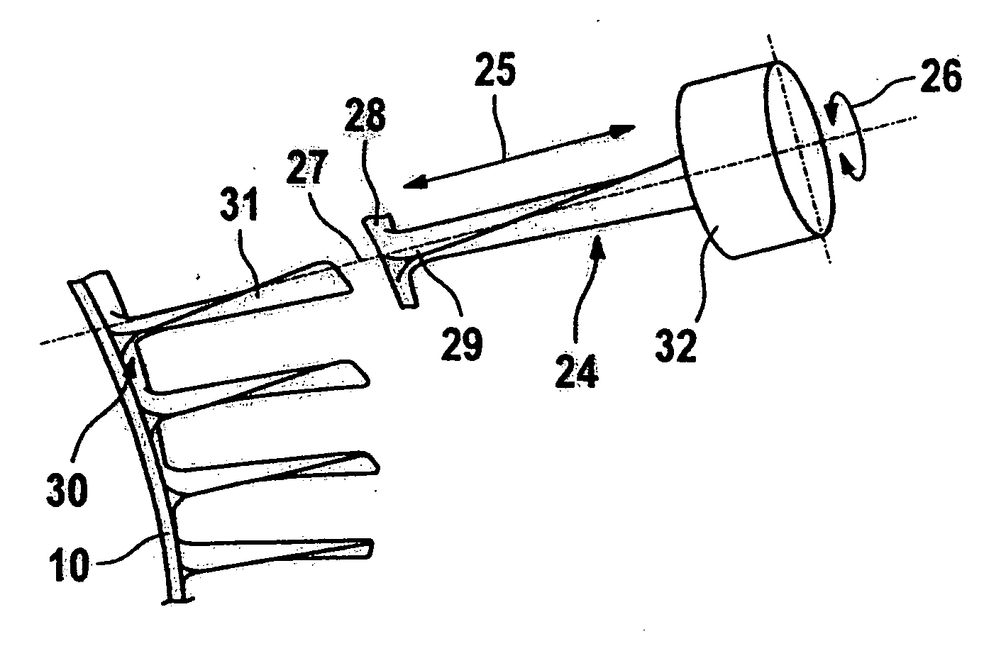
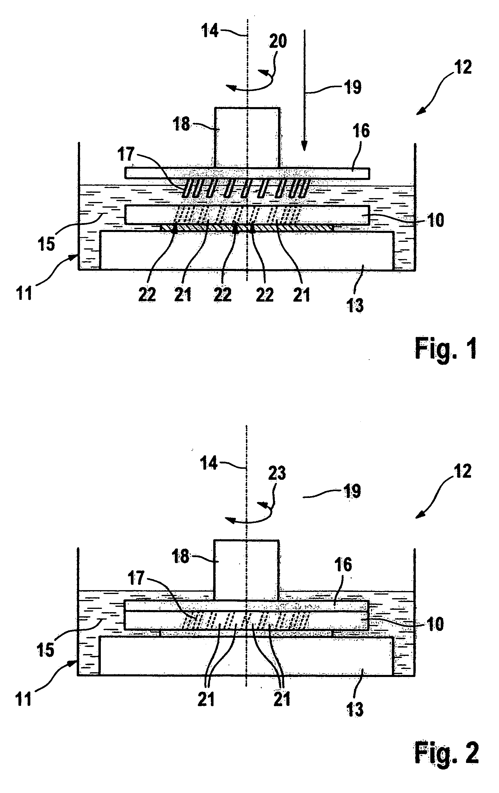
[0018] To manufacture an integrally bladed rotor according to the present invention, a basic rotor body 10 is provided, basic rotor body 10 being positioned in a receptacle 111 of a device labeled overall with the reference number 12 for manufacturing an integrally bladed rotor.

[0019] Receptacle 11 of device 12 includes a holding device 13, on which basic rotor body 10 is placed. Basic rotor body 10 is rotatably mounted on holding device 13. According to FIG. 1, basic rotor body 10 is positioned on the holding device in such a way that a longitudinal central axis 14 of basic rotor body 10 extends in the vertical direction. A radial direction of basic rotor body 10 will then extend horizontally when basic rotor body 10 is placed on holding device 13 as shown in FIG. 1. As FIG. 1 shows, receptacle 11 is used both for mounting basic rotor body 10 and for receiving an electrolyte 15, which is required for the subsequent electrochemical machining (ECM) of basic rotor body 10.

[0020] Dev...


PUM

PropertyMeasurementUnit
pressureaaaaaaaaaa
axis of rotationaaaaaaaaaa
sizeaaaaaaaaaa

Abstract

A method for manufacturing integrally bladed rotors (preferably gas turbine rotors) is provided. The method includes the steps of a) providing a basic rotor body; b) placing the basic rotor body into an electrolyte; c) electrochemically machining the basic rotor body by simultaneously manufacturing a plurality of unmachined blades; and d) subsequently machining the unmachined blades to provide hydrodynamic surfaces, in particular a suction side and a pressure side, in the area of each unmachined blade.

Description

[0001] Priority is claimed to German Application Serial No. DE 10 2004 051 854.8, filed Oct. 26, 2004, the entire disclosure of which is hereby incorporated by reference herein. FIELD OF THE INVENTION [0002] The present invention relates to a method for manufacturing integrally bladed rotors, gas turbine rotors in particular. Furthermore, the present invention relates to a device for manufacturing integrally bladed rotors, gas turbine rotors in particular. BACKGROUND [0003] Rotors such as gas turbine rotors have a basic rotor body and a plurality of rotor blades. The rotor blades are either anchored in appropriate recesses of the basic rotor body via blade feet or are integral components of the basic rotor body. Integrally bladed rotors are referred to as blisks (bladed disk) or blings (bladed ring), depending on whether a disk-shaped or ring-shaped basic rotor body is used. The present invention relates to a method and a device for manufacturing a rotor having integral blades. [000...

Claims


Application Information

Patent Timeline
Patent Type & Authority Applications(United States)
IPC IPC(8): B23P13/04
CPCB23H9/10Y10T29/49995Y10T29/49325
Inventor BAYER, ERWINBUSSMANN, MARTINKRAENZLER, THOMASPLATZ, ALBINSTEINWANDEL, JUERGEN
Owner MTU AERO ENGINES GMBH
Why Eureka
Try Eureka