
AC generator with independently controlled field rotational speed

a generator and independent control technology, applied in the direction of synchronous generators, electric generator control, control systems, etc., can solve the problems of increasing maintenance frequency, increasing overall aircraft, fuel and maintenance costs, and large hydroelectric transmissions

Inactive Publication Date: 2006-04-27
HONEYWELL INT INC
View PDF34 Cites 43 Cited by
  • Summary
  • Abstract
  • Description
  • Claims
  • Application Information

AI Technical Summary

Problems solved by technology

For example, hydraulic transmissions can be relatively large, heavy, complex, and / or may exhibit relatively poor reliability.
Each of these factors can lead to increased overall aircraft, fuel, and maintenance costs, and / or increased maintenance frequency, which can further lead to increased costs.
Although this solution does work, it also suffers certain drawbacks in that the main and auxiliary windings are arranged to be magnetically decoupled by having a specified numbers of poles that are configured such that one pole of one set of windings encompasses one or more pairs of poles of the other set of windings.
This can lead to complexity in design and implementation.

Method used


Image

  • AC generator with independently controlled field rotational speed
  • AC generator with independently controlled field rotational speed
  • AC generator with independently controlled field rotational speed

Examples


Embodiment Construction

[0016] The following detailed description of the invention is merely exemplary in nature and is not intended to limit the invention or the application and uses of the invention. Furthermore, there is no intention to be bound by any theory presented in the preceding background of the invention or the following detailed description of the invention.

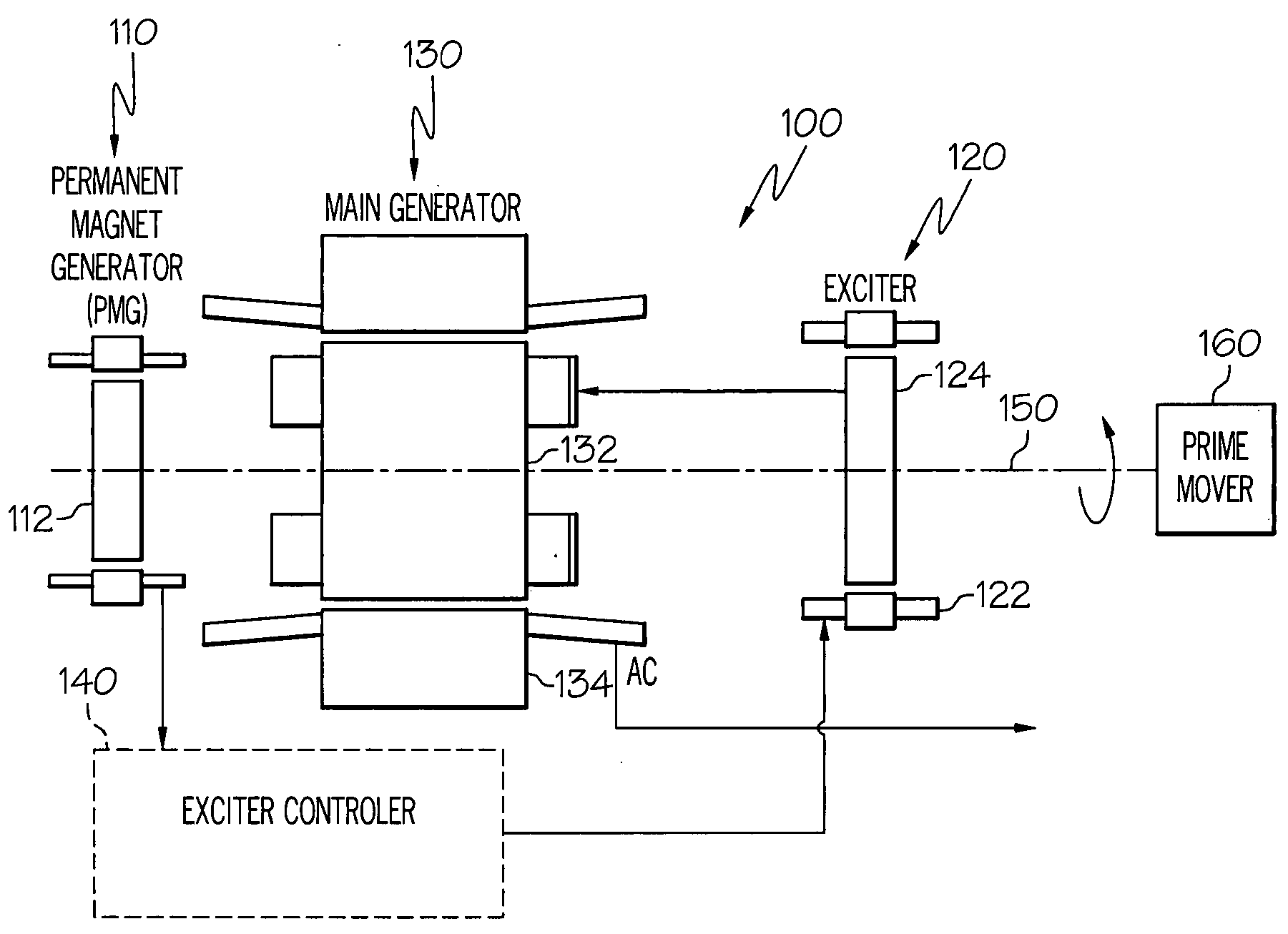
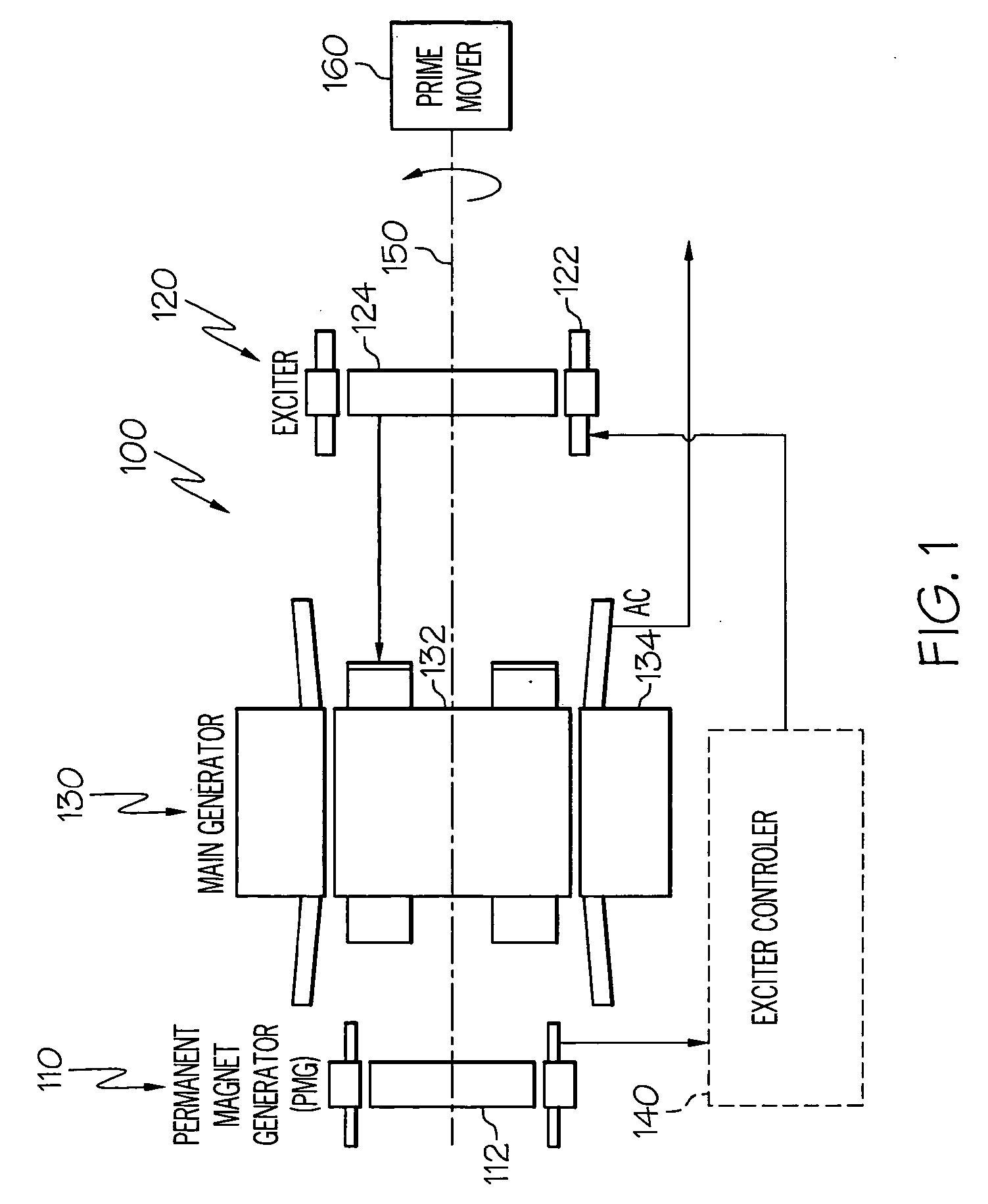
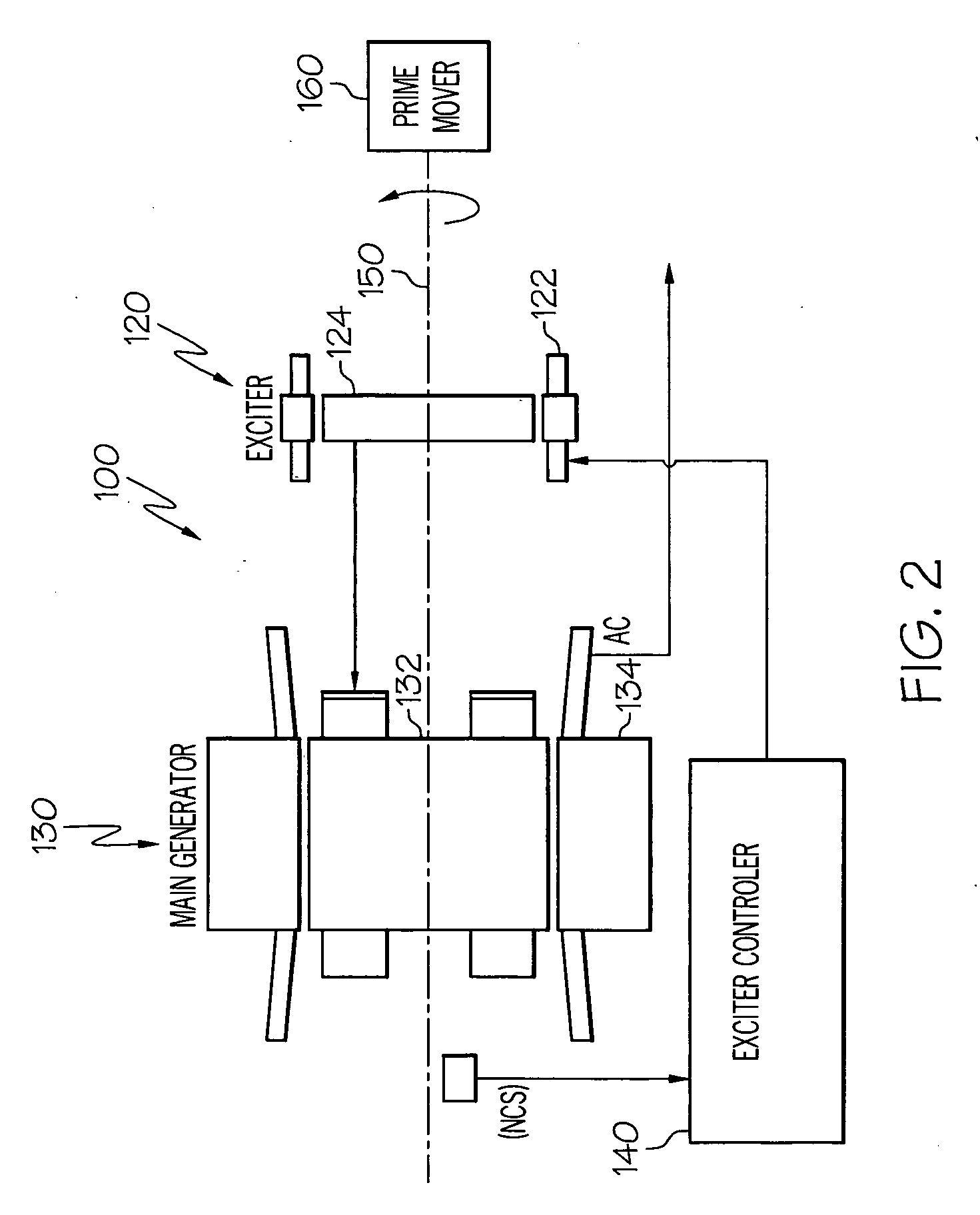
[0017] Turning now to the description and with reference first to FIG. 1, a functional schematic block diagram of an exemplary high speed generator system 100 for use with, for example, an aircraft gas turbine engine, is shown. This exemplary generator system 100 includes a permanent magnet generator (PMG) 110, an exciter 120, a main generator 130, and an exciter controller 140. It will be appreciated that the generator system 100 may include one or more additional components, sensors, or controllers. However, a description of these additional components, sensors, and controllers, if included, is not needed, and will therefore not be furth...


PUM


Abstract

A generator system is configured to supply relatively constant frequency AC power when driven by a variable speed prime mover, by independently controlling the main rotor flux rotational speed. The generator system includes an exciter stator that induces current in the exciter rotor windings at a desired frequency and phasing. The exciter rotor windings are electrically connected to the main rotor windings, and are thus electrically excited at the same frequency and phasing. Excitation is supplied to the exciter stator from an exciter controller, which controls the frequency and phasing of the exciter excitation, based on the rotational speed of the generator, to maintain a constant output frequency.

Description

CROSS-REFERENCES TO RELATED APPLICATIONS [0001] This application claims the benefit of U.S. Provisional Application No. 60 / 622,495, filed Oct. 26, 2004.TECHNICAL FIELD [0002] The present invention relates to AC generators and, more particularly, to AC generators with independently controlled field rotational speeds, to thereby supply a relatively constant frequency AC voltage under varying mechanical rotational speeds. BACKGROUND [0003] Many aircraft include AC generator systems to supply relatively constant frequency AC power. Many of the AC generator systems installed in aircraft include three separate brushless generators, namely, a permanent magnet generator (PMG), an exciter, and a main generator. The PMG includes a rotor having permanent magnets mounted thereon, and a stator having a plurality of windings. When the PMG rotor rotates, the permanent magnets induce AC currents in PMG stator windings. These AC currents are typically fed to a regulator or a control device, which in...

Claims


Application Information

Patent Timeline
IPC IPC(8): H02P9/10H02P9/14
CPCH02K19/26H02K19/38H02P2101/30H02P9/48H02P9/007
Inventor XU, MINGZHOUBENSON, DWAYNE M.PEARSON, WAYNE T.
Owner HONEYWELL INT INC
Learn More