Pressure-detecting sensor

Inactive Publication Date: 2006-04-27
AISIN SEIKI KK
View PDF3 Cites 13 Cited by
  • Summary
  • Abstract
  • Description
  • Claims
  • Application Information

AI Technical Summary

Problems solved by technology

If an obstacle is pinched between a door frame and the door panel under closing movement, the outer cover is deformed, which causes the lead electrodes to contact.
In addition, in the above mentioned cord switch, there is a time lag between the beginning of the pinched condition and the contact of the electrodes, resulting in delayed reversing the door panel.
Such an expected reaction may occur if the cord switch is mounted to the door panel with an excessive pressure.

Method used


Image

  • Pressure-detecting sensor
  • Pressure-detecting sensor
  • Pressure-detecting sensor

Examples


first embodiment

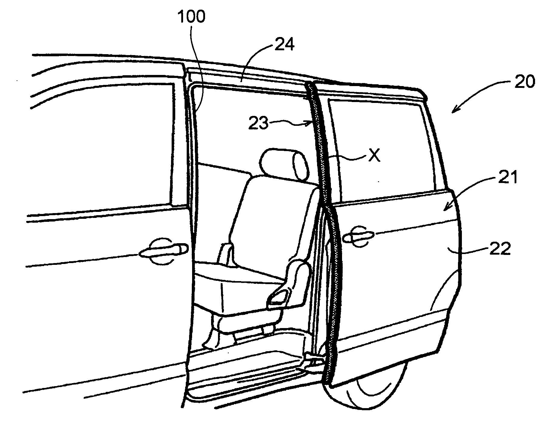
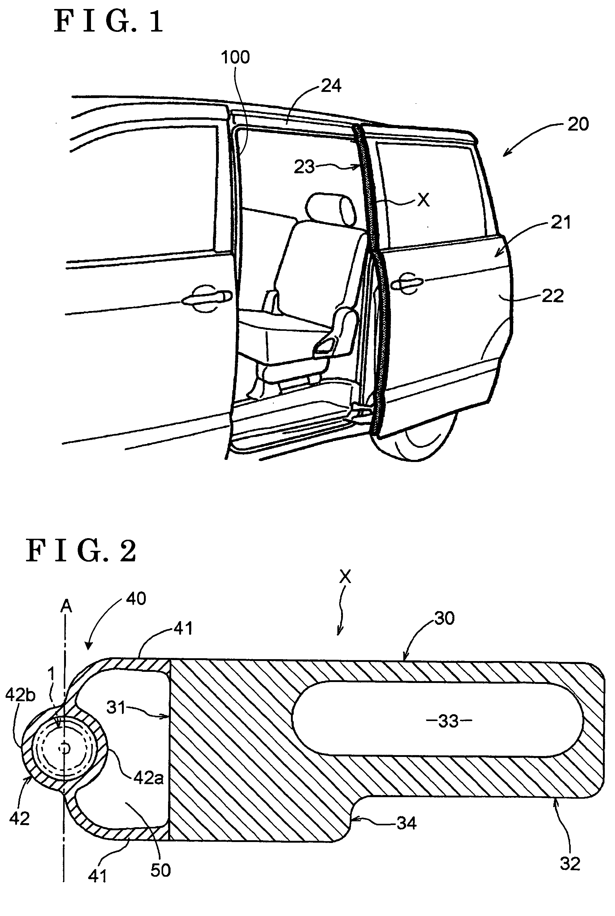
[0019] First of all, referring to FIG. 1, there is illustrated a van or vehicle 20 to which is provided a pressure sensitive sensor X of the present invention. In detail, the van 20 has at its rear portion a door opening 24 that is opened and closed by an electrically operated sliding door 21 that includes a door panel 22. The door panel 22 has at its front end a vertically extending edge portion 23 along which the pressure sensitive sensor X is provided. The door opening 24 is defined by a frame 100. The door panel 22 is mounted on the frame 100 so as to be moved in the vehicular lengthwise direction.

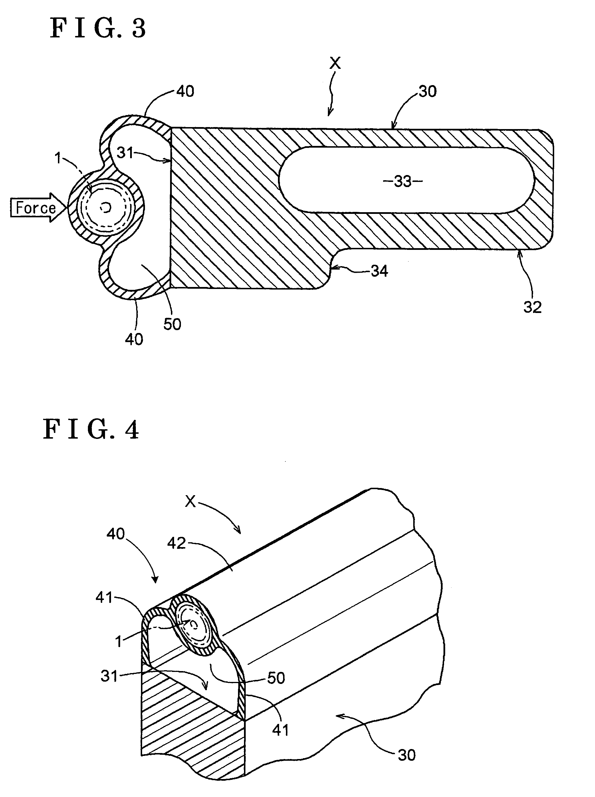
[0020] As shown in FIGS. 2 through 4, the pressure sensitive sensor X is, as a whole, formed into an elongate structure and is designed to react when a piezoelectric sensor 1, which is mounted to a base member 30 via a supporting member 40, abuts with an obstacle (not shown). The piezoelectric sensor 1 is capable of detecting an object by bending somewhat when being contact with the ob...

second embodiment

[0035] Referring to FIG. 6, there is illustrated the present invention, wherein the pair of the legs 41 and 41 extends from the cylindrical portion 42 to the base member 30 after running along the plane A. Such a structure avoids that collision direction equals the extending direction of the leg 41, which makes the legs 41 and 41 much easier than the FIG. 2-structure.

third embodiment

[0036] With reference to FIG. 7, the present invention is illustrated wherein each of the legs 41 and 41 is formed therein with a plurality of lengthwise equally pitched slits 43. Such a structure provides a partial deformation of the leg 41, resulting in that a portion of the leg 41 that is near the pinched obstacle is made to deform, thereby reacting the piezoelectric sensor 1 very quickly.


PUM


Abstract

A pressure sensitive sensor includes a base member, a supporting member connected to one end of the base member and deformable upon receipt of a pressure, and a piezoelectric sensor provided in the supporting member.

Description

CROSS-REFERRENCE TO RELATED APPLICATION [0001] This application is based on and claims priority under U.S.C.§119 to Japanese Patent Application 2004-313068, filed on Oct. 27, 2004, the entire content of which is incorporated herein by reference. FIELD OF THE INVENTION [0002] The present invention is directed to a pressure sensitive sensor having a sensor element that is connected to a base member via a supporting member and designed to react upon collision with an obstacle. BACKGROUND OF THE INVENTION [0003] In a sliding door device for vehicles, an electrically operated doorframe is provided at one side of a vehicle body for opening and closing door opening. Sometimes an obstacle such as a part of human body or foreign matter may be pinched between the door panel under closing movement and a doorframe defining the door opening. In such a case, for immediate release of the pinched condition, the door movement is controlled to reverse upon detection of the obstacle by a pressure sens...

Claims


Application Information

Patent Timeline
IPC IPC(8): B60Q1/00
CPCB60J5/06E05F15/42E05Y2800/67E05Y2900/531
Inventor TAKEUCHI, MASAYOSHI
Owner AISIN SEIKI KK
Why Eureka
Try Eureka