Integrated pressure sensitive lens assembly

a technology of pressure sensitive lenses and integrated components, which is applied in the field of touch sensitive input panels or displays, can solve the problems of user fatigue, reduced clarity, and a fixed amount of pressure by the finger

Active Publication Date: 2010-02-25
APPLE INC
View PDF9 Cites 173 Cited by
  • Summary
  • Abstract
  • Description
  • Claims
  • Application Information

AI Technical Summary

Benefits of technology

[0019]Accordingly, it is an object of the present invention to provide a low-cost pressure sensitive touch sen

Problems solved by technology

The disadvantage of a resistive pad is that it requires a fixed amount of pressure by a finger in order to make the contact between the two conductive plates.
This leads to user fatigue due to non-user optimized touch screen sensitivity.
The resistive membrane will also wear out, initially resulting in further reduced clarity followed by dead spots.
Capacitive pads are relatively expensive to manufacture, and can only detect objects with sufficient

Method used


Image

  • Integrated pressure sensitive lens assembly
  • Integrated pressure sensitive lens assembly
  • Integrated pressure sensitive lens assembly

Examples


Embodiment Construction

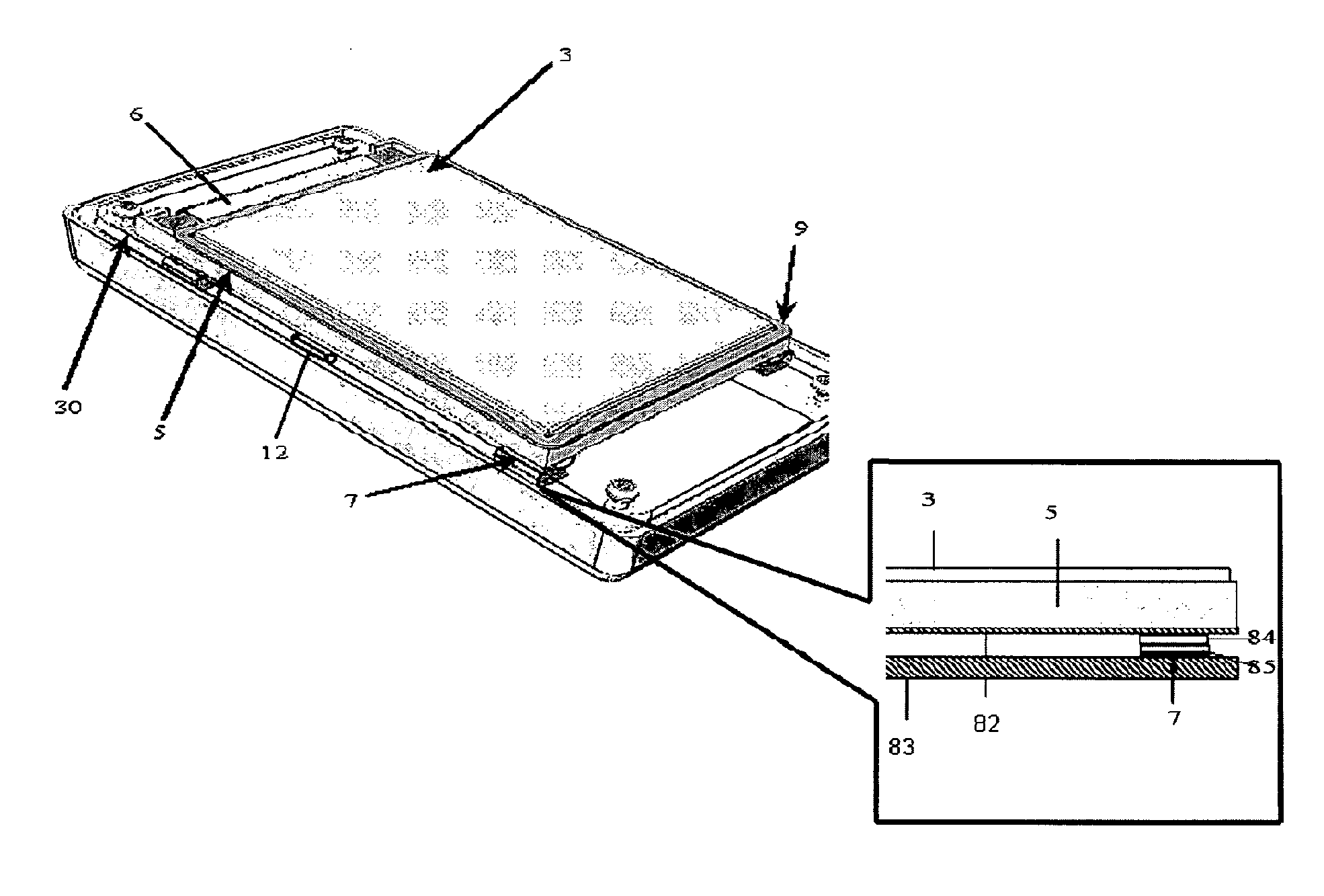
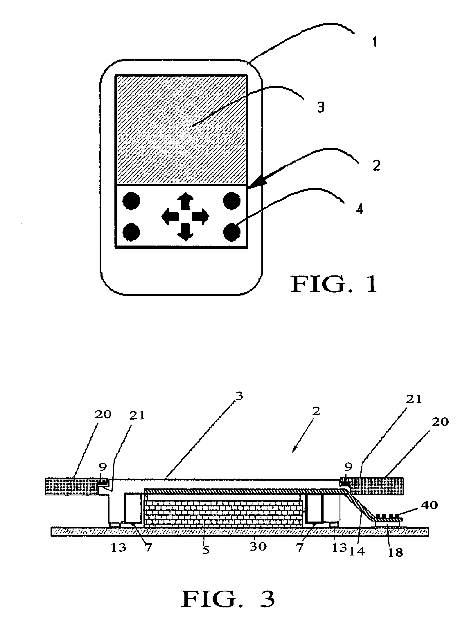
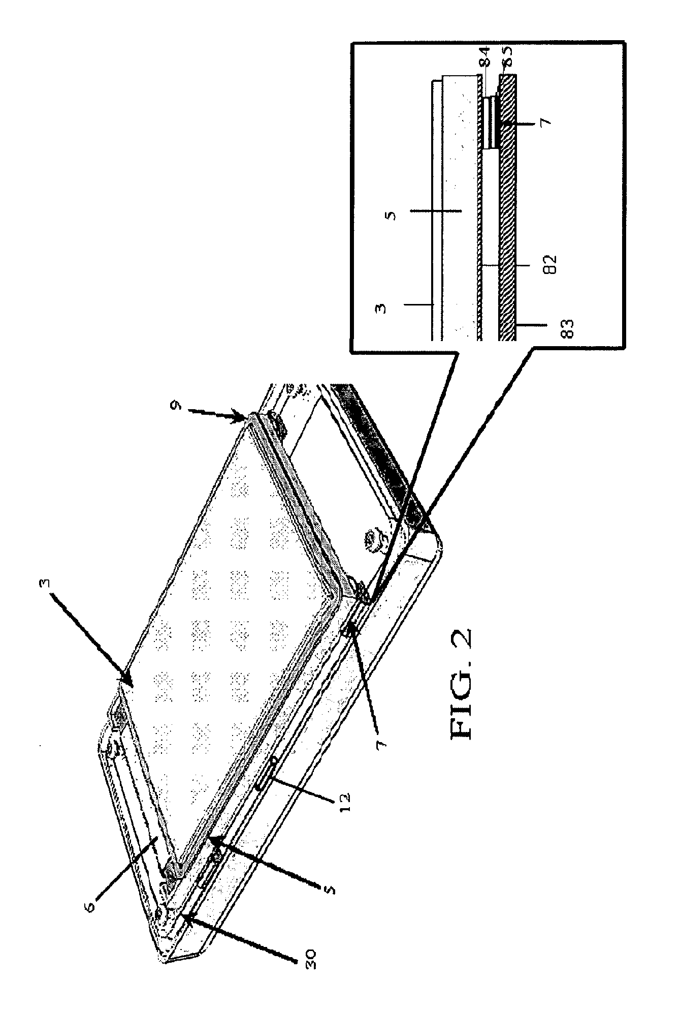
[0035]The present invention is a touch sensitive display for an electronics device such as cell phones, PDAs, desktop phones, tablets, copy machines, or any other device that uses touch sensitive displays or panels including LCD or Organic Light-Emitting Diode (OLED) display screens.

[0036]Generally, the invention comprises a plurality (such as, for example, four) differentially-mounted pressure sensors to detect the force imparted to a primary touch surface. Two basic mechanical embodiments are disclosed. In one embodiment the sensors are mounted beneath the display module itself. Most conventional display screens (LCD or otherwise) are reinforced with a bonded protective lens. This lens is typically a 0.70 mm to 1.2 mm treated glass, protecting the LCD against cracks, scratching and also providing anti-glare coating. The existing glass lens serves as the primary touch surface, and the force imparted to the primary touch surface is transmitted through the display module and is detec...


PUM


Abstract

A touch screen assembly for an electronic device such as a cell phone or PDA. The touch screen assembly generally comprises a floating lens suspended over the display and, optionally, the keypad to allow a degree of freedom. An underlying thin connecting layer such as a flex film is attached beneath the floating lens, and a plurality (for example, four) differentially-mounted pressure sensors are mounted beneath the floating lens and are electrically connected to the electronic device via the flex film. The pressure sensors are differentially positioned along an x- and y-axis for registering a pressure z from a touch to the lens at each of the four positions, to provide four data sets (x1-4, y1-4, z1-4). Control software then interprets the exact touch-coordinate from the four data sets and generates a control signal. An optional haptic response generator and/or motion sensor are also contemplated. When used in a smaller electronics device such as a cell phone or PDA the touch screen sensor technology of the present invention is exceedingly thin and is capable of modular assembly for more-or-less “snap-in” construction.

Description

BACKGROUND OF THE INVENTION[0001]1. Field of the Invention[0002]The present invention relates to input devices for electronics and, more particularly, to a touch sensitive input panel or display with small form factor especially suited for use in cellular phones and personal digital assistants (PDAs), PC Tablets, as well as laptops, PCs, office equipment, medical equipment, or any other device that uses touch sensitive displays or panels.[0003]2. Description of the Background[0004]Touch screens have been deployed in many products in recent years.[0005]There are several types of technology used in implementing touch sensitive screens that can detect the application of fingers and other passive objects.[0006]For example, resistive pads comprise two conductive plates pressed together. The disadvantage of a resistive pad is that it requires a fixed amount of pressure by a finger in order to make the contact between the two conductive plates. This leads to user fatigue due to non-user op...

Claims


Application Information

Patent Timeline
IPC IPC(8): G06F3/041
CPCG06F1/1626G06F1/1643G06F1/1658H04M2250/22G06F3/016G06F3/0414G06F3/0416G06F1/169G06F3/04142G06F3/0412
Inventor MOLNE, ANDERS
Owner APPLE INC
Why Eureka
Try Eureka