Double-side thermally conductive adhesive tape for plastic-packaged electronic components

a technology of thermally conductive adhesive and electronic components, which is applied in the direction of transportation and packaging, laminating printed circuit boards, and improving the adhesion of metals to insulating substrates, etc., can solve the problems of increasing the complexity of the design, the size of the device has continued to shrink, and the circuit design of modem electronic devices such as televisions, radios, etc., to facilitate the dispensing and application of such adhesive tapes

Inactive Publication Date: 2002-08-13
PARKER INTANGIBLES LLC
View PDF13 Cites 182 Cited by
  • Summary
  • Abstract
  • Description
  • Claims
  • Application Information

AI Technical Summary

Benefits of technology

In a preferred embodiment, the second PSA composition is formulated as an acrylic-based PSA which is rendered thermally conductive via its loading with a thermally-conductive particulate filler such as an aluminum oxide. The first PSA composition, in turn, is preferably is formulated as a silicone-based PSA which, optionally, is rendered thermally conductive via its loading with a thermally-conductive, particulate filler such as an aluminum oxide. For ease of handling and application, the adhesive layers may be coated on respective sides of a carrier interlayer, such as a polymeric film or a metal foil, to form a tape which may be faced on one or both sides with a release liner and then wound on a roll. In use, individual interface elements may be machine or manually cut from the roll as configured to conform to the margins of the associated heat transfer surfaces of, for example, the electronic component and heat sink. Then, with the release liner or liners removed, each side of the tape may be adhered under pressure to the corresponding heat transfer surface of the electronic component or heat sink. Optionally, the surfaces of the adhesives layers may be embossed with a cross-hatched pattern, as is shown in the commonly-assigned U.S. Pat. Nos. 5,213,868 and 5,298,791, for additional conformably to the heat transfer surfaces with minimal air pockets.
Advantages of the present invention include an interface material that may be provided in the form of a double-sided, pressure sensitive adhesive tape, and that is particularly adapted for bonding a low surface energy substrate, such as a plastic packaged electronic component, without the use of a primer to a metal heat sink or chassis wall. Additional advantages include a double-sided, thermally-conductive adhesive tape which may be provided in a roll for automated application, and which can be consistently applied using either automated or manual processes for precise thermal and adhesive properties. Still further advantages include a thermal interface offering an easy "peel and stick" installation without the use of mechanical fasteners such as clips or screws. Yet further advantages include a thermal interface that can be removed after application for repair or rework. These and other advantages will be readily apparent to those skilled in the art based upon the disclosure contained herein.
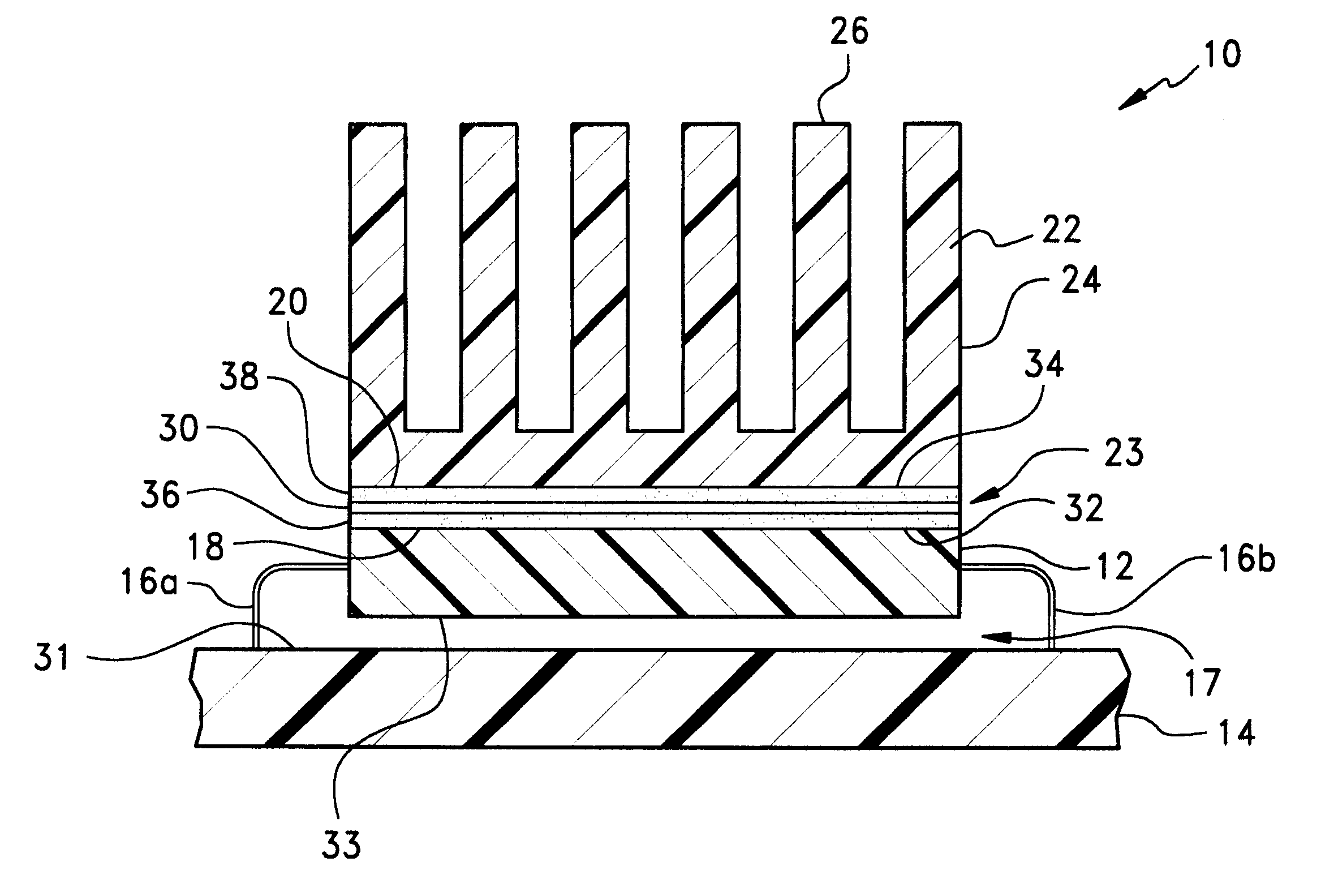
With the first heat transfer surface 18 of electronic component 12 disposed in opposing thermal adjacency with second heat transfer surface 20 of dissipation member 22, a sheet, pad, or other layer of a thermally-conductive interface, 30, is interposed therebetween within interfacing region 23 for providing a conductive pathway for the transfer of thermal energy from component 12 to dissipation member 20. By "thermally conductive," it is meant that the interface exhibits a thermal conductivity of between about 0.1 W / m-.degree.K and about 1 W / m-.degree.K. The pathway provided by interface 30 may be employed without or in conjunction with convective air circulation for effecting the cooling of component 12 and ensuring that the operating temperature thereof is maintained below specified limits. As may be seen in the cross-sectional view provided, interface 30 is both complaint and conformable within interfacing region 23 for the exclusion of air pockets or other voids therefrom. That is, interface 30 advantageously improves the efficiency and rate of heat transfer through the interfacing region by filling in the region to provide a generally continuous interface between the component 12 and the dissipation member 22, and by substantially conforming to the heat transfer surfaces 18 and 20 thereof. Although thermal dissipation member 22 is shown to be a separate heat sink member, board 14 itself may be used for such purpose by alternatively interposing interface 30 between surface 31 thereof and corresponding surface 33 of electronic component 12.
With first and second heat transfer surfaces 18 and 20 being formed, respectively, of a plastic and a metal material, it is preferred that the first PSA composition is formulated as a silicone-based PSA component or resin optionally blended with a thermally-conductive filler, with the second PSA component being formulated as a blend of an acrylic-based PSA component or resin and a thermally-conductive filler. In this regard, acrylic PSA's are known to exhibit strong adhesion to a variety of substrates including metal surfaces. However, due to their polar nature, acrylic PSA's generally exhibit relatively poor adhesion to low surface energy substrates as typified by polyolefins. For example, commercial acrylic PSA's have been observed to exhibit a 180.degree. peel adhesion on untreated polyethylene of less than 0.5 lb / in. Silicone PSA's, in contrast, do exhibit good adhesion to low surface energy substrates such as polyolefins and other plastics. Advantageously, the use of two different PSA formulations facilitates that attachment of dissipation member 22 to component 12 without the use of a clip, spring, or clamp or the like which otherwise would have to be provided for applying an external force to develop an interface area contact between the interface 30 and surfaces 18 and 22.
Additional fillers and additives may be included in the formulation depending upon the requirements of the particular application envisioned and to the extent that the thermal conductivity and electrical properties of the formulation are not overly compromised. Such fillers and additives may include conventional wetting, opacifying, or anti-foaming agents, chain extending oils, tackifiers, pigments, lubricants, stabilizers, flame retardants such as decabromodiphenyl oxide, and antioxidants. A solvent or other diluent may be employed during the compounding of the formulation to lower the viscosity of the material for improved mixing.
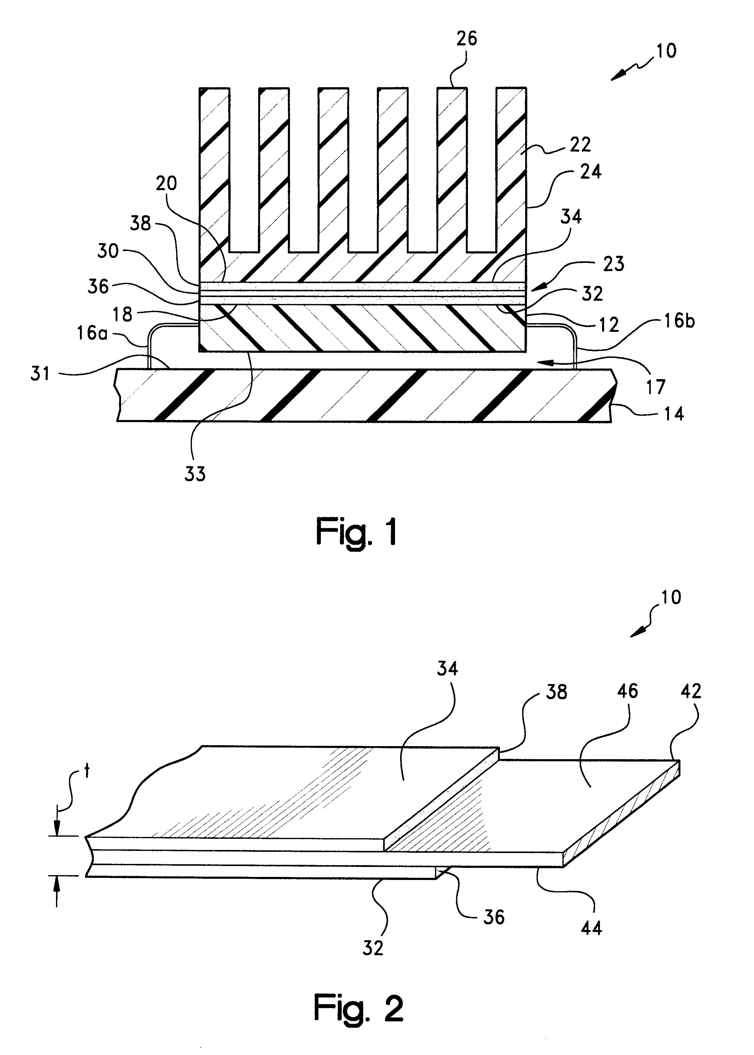
Turning to FIG. 2, a preferred embodiment of interface 30 is shown at 40 to be provided as a length of a laminated, double-sided tape including an optional interlayer carrier or reinforcement member, 42, which is incorporated as a substrate within the tape. Conventionally, reinforcement member 42, which improves the physical strength of the tape for handling, die-cutting, and the like, may be provided as a film formed of a thermoplastic material such as a polyimide, a layer of a woven fiberglass fabric or cloth, or an aluminum or other metal foil, screen, or expanded mesh. Reinforcement member 42 typically will have a thickness of from about 0.0005-0.005 inch (0.0127-0.127 mm), with a thickness of about 0.002 in (0.050 mm) being preferred for metal foils.

Problems solved by technology

Circuit designs for modem electronic devices such as televisions, radios, computers, medical instruments, business machines, communications equipment, and the like have become increasingly complex.
Although the complexity of the designs has increased, the size of the devices has continued to shrink with improvements in the ability to manufacture smaller electronic components and to pack more of these components in an ever smaller area.
As electronic components have become smaller and more densely packed on integrated boards and chips, designers and manufacturers now are faced with the challenge of how to dissipate the heat which is ohmicly or otherwise generated by these components.
Indeed, it is well known that many electronic components, and especially power semiconductor components such as transistors and microprocessors, are more prone to failure or malfunction at high temperatures.
Thus, the ability to dissipate heat often is a limiting factor on the performance of the component.
For high power circuits and the smaller but more densely packed circuits typical of current electronic designs, however, simple air circulation often has been found to be insufficient to adequately cool the circuit components.
These pockets reduce the overall surface area contact within the interface which, in turn, reduces the heat transfer area and the overall efficiency of the heat transfer through the interface.
Moreover, as it is well known that air is a relatively poor thermal conductor, the presence of air pockets within the interface reduces the rate of thermal transfer through the interface.
The greases and waxes of the aforementioned types heretofore known in the art, however, generally are not self-supporting or otherwise form stable at room temperature and are considered to be messy to apply to the interface surface of the heat sink or electronic component.
Moreover, use of such materials typically involves hand application or lay-up by the electronics assembler which increases manufacturing costs.
However, the thermal interface materials previously known in the art were designed for use with ceramic substrates, and not for use with the low surface energy, plastic substrates now common in the commercial electronics market.

Method used


Image

  • Double-side thermally conductive adhesive tape for plastic-packaged electronic components
  • Double-side thermally conductive adhesive tape for plastic-packaged electronic components
  • Double-side thermally conductive adhesive tape for plastic-packaged electronic components

Examples


example 1

A thermally-conductive interface laminate was prepared according to the presented invention for characterization by cold nipping a 2-3 mil (0.05-0.075 mm) layer of an acrylic PSA component (H&N Chemicals Polytack.TM. 100 LV) blended with about 50% by weight of tabular aluminum oxide (Alcoa, Pittsburgh, Pa.) onto a first side of a 0.002 in (0.050 mm) thick aluminum foil carrier. Onto the second side of the carrier was cold nipped a 2-3 mil (0.05-0.075 mm) layer of a silicone PSA component (Adhesives Research 8026) to form a double-sided PSA tape. Such tape was observed to exhibit the following physical properties:

These and other physical properties will vary, of course, with the filler loading level and with the use of optional additives.

example 2

Comparative double-sided, thermally-conductive interface tape systems were prepared to confirm the precepts of the present invention. In each of the systems, a 2.5-3 mil (0.056-0.075 mm) thick layer of an acrylic-based PSA component (H&N Chemicals Polytack.TM. 100 LV) blended with about 50% by weight of alumina was nipped onto a first side of a 0.002 in (0.050 mm) thick aluminum foil carrier. In a first system identified as "Sample A" in Table 2 which follows, a 1 mil (0.025 mm) layer of an unfilled, first silicone-based PSA component (Adhesives Research 8026) was nipped onto the second side of one of the carriers. Similarly, in a second system identified as "Sample B" in Table 2, a 1 mil (0.025 mm) layer of an unfilled, second silicone-based PSA component (Flexcon 1078) was nipped onto the second side of the other one of the carriers. The physical properties, namely 90.degree. peel (ASTM D1000), lap shear (ASTM D1002) under different bond pressures, creep adhesion (PSTC #7), and di...


PUM

PropertyMeasurementUnit
thicknessaaaaaaaaaa
thicknessaaaaaaaaaa
surface energyaaaaaaaaaa

Abstract

A thermally conductive interface, which may be in the form of a double-sided, pressure sensitive adhesive tape, disposable intermediate a heat-generating source having a first heat transfer surface formed of a first material having a low surface energy, and a thermal dissipation member having a second heat transfer surface which is formed of a second material having a surface energy substantially higher than the surface energy of the first material, and which is disposable opposite the first heat transfer surface of the heat-generating source in a spaced-apart, heat transfer adjacency therewith. The interface includes a first pressure sensitive adhesive (PSA) surface which is bondable under pressure to at least a portion of the first heat transfer surface of the heat-generating source, and an opposing second pressure sensitive adhesive (PSA) surface bondable under pressure to at least a portion of the second heat transfer surface of the heat-generating source. The first PSA surface is presented from a layer of a thermally-conductive, first pressure sensitive adhesive composition, preferably silicone-based, having an affinity to the first heat transfer surface of the heat generating source. In turn, the second PSA surface is presented from a layer of a second pressure sensitive adhesive composition, preferably acrylic-based, different from the first composition and having an affinity to the second heat transfer surface of the thermal dissipation member. The interface is particularly adapted for bonding a plastic packaged electronic component to a metal heat sink.

Description

The present invention relates broadly to a thermal management material which is interposable as an interface between, for example, the heat transfer surfaces of a heat-generating, electronic component, such as an integrated circuit (IC) chip, and a thermal dissipation member, such as a heat sink or circuit board, for the conductive cooling of the electronic component. More particularly, the invention relates to a double-side, pressure sensitive adhesive tape adapted for attaching a metal heat sink to a plastic-encapsulated or "packaged," heat-generating electronic component.Circuit designs for modem electronic devices such as televisions, radios, computers, medical instruments, business machines, communications equipment, and the like have become increasingly complex. For example, integrated circuits have been manufactured for these and other devices which contain the equivalent of hundreds of thousands of transistors. Although the complexity of the designs has increased, the size o...

Claims


Application Information

Patent Timeline
Patent Type & Authority Patents(United States)
IPC IPC(8): H01L23/36H01L23/373H01L23/34H05K1/05H05K3/00H05K3/38
CPCH01L23/36H01L23/3737H01L2924/3011H05K1/05H05K3/0058H05K3/386H01L2224/32245Y10T428/14Y10T428/2848Y10T428/1405Y10T428/1481Y10T428/24273Y10T428/24322
Inventor BUNYAN, MICHAEL H.
Owner PARKER INTANGIBLES LLC
Why Eureka
Try Eureka