
Modulation and demodulation system, modulator, demodulator and phase modulation method and phase demodulation method used therefor

Inactive Publication Date: 2006-04-27
NEC CORP
View PDF4 Cites 7 Cited by
  • Summary
  • Abstract
  • Description
  • Claims
  • Application Information

AI Technical Summary

Benefits of technology

[0044] When converting the binary signal of length b-m to the ternary signal of length m, it associates the binary signal of length b-m with the ternary signal of length m to reduce a mean error rate of each bit of the binary signal of length b-m corresponding to all the errors of the Lee distance 1 of the ternary signal of length m so as to convert the binary signal of length b to the senary signal of length m.
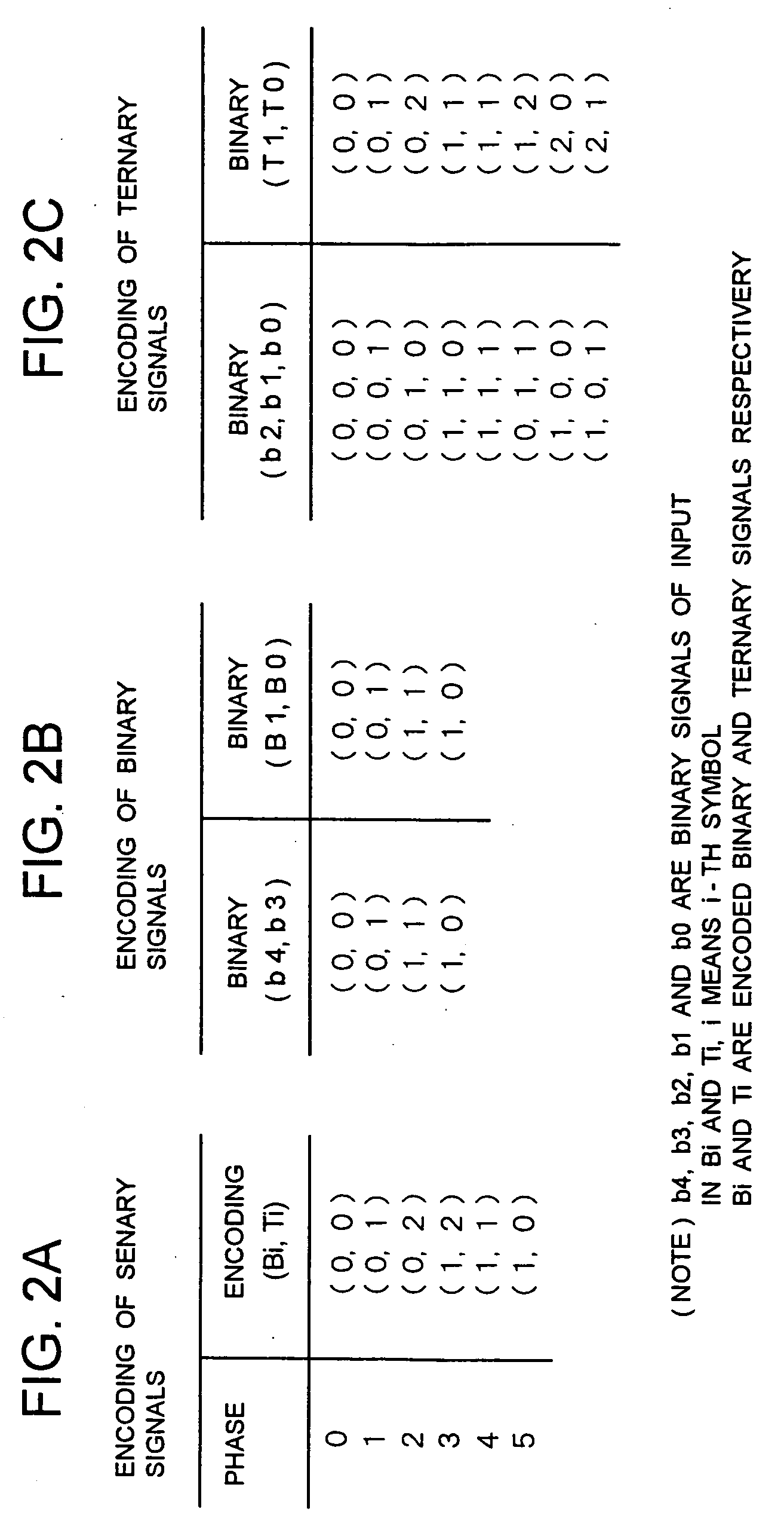
[0052] In six-phase phase modulation, the data conversion portion for converting the binary signal of length b to the senary signal of length m includes means for converting the binary signal of length b-m to the ternary signal of length m, and the first to sixth phases are expressed as (B, T) by using binary signal B and ternary signal T, which are (0, 0), (0, 1), (0, 2), (1, 2), (1, 1) and (1, 0) so as to render Hamming distances between (0, 2) and (1, 2) and between (1, 0) and (0, 0) as 1. Therefore, in the six-phase phase modulation, the Hamming distances are smaller compared to the case of (0, 0), (0, 1), (0, 2), (1, 0), (1, 1), (1, 2) so that the bit error rate can be reduced.
[0053] The means for converting the binary signal of length b-m to the ternary signal of length m associates the binary signal of length b-m with the ternary signal of length m to reduce the mean error rate of each bit of the binary signal of length b-m corresponding to all the errors of Lee distance 1 of the ternary signal of length m. Thus, the Hamming distances are smaller between (0, 0) and (0, 1), between (0, 1) and (0, 2), between (1, 2) and (1, 1) and between (1, 1) and (1, 0) respectively so that the bit error rate can be reduced.
[0091] Thus, the modulation and demodulation system of the present invention can minimize the bit error rate in the six-phase phase modulation method and also simplify the circuit configuration in the six-phase phase modulation method.
[0092] The modulation and demodulation system of the present invention can have the effect of minimizing the bit error rate in the six-phase phase modulation method by having the configuration and operation described hereunder.
[0093] The other modulation and demodulation system of the present invention can have the effect of simplifying the circuit configuration in the six-phase phase modulation by having the following configuration and operation.

Problems solved by technology

In the case of applying the gray encoding to the six-phase phase modulation, however, there is a problem that the bit error is not minimized per the symbol error.
Consequently, there is a problem that the six-phase phase modulation applied conventional coding such as gray coding has an inferior error rate characteristic.

Method used


Image

  • Modulation and demodulation system, modulator, demodulator and phase modulation method and phase demodulation method used therefor
  • Modulation and demodulation system, modulator, demodulator and phase modulation method and phase demodulation method used therefor
  • Modulation and demodulation system, modulator, demodulator and phase modulation method and phase demodulation method used therefor

Examples


example

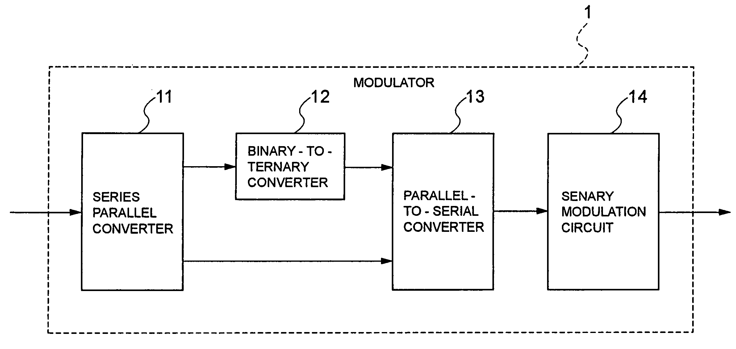
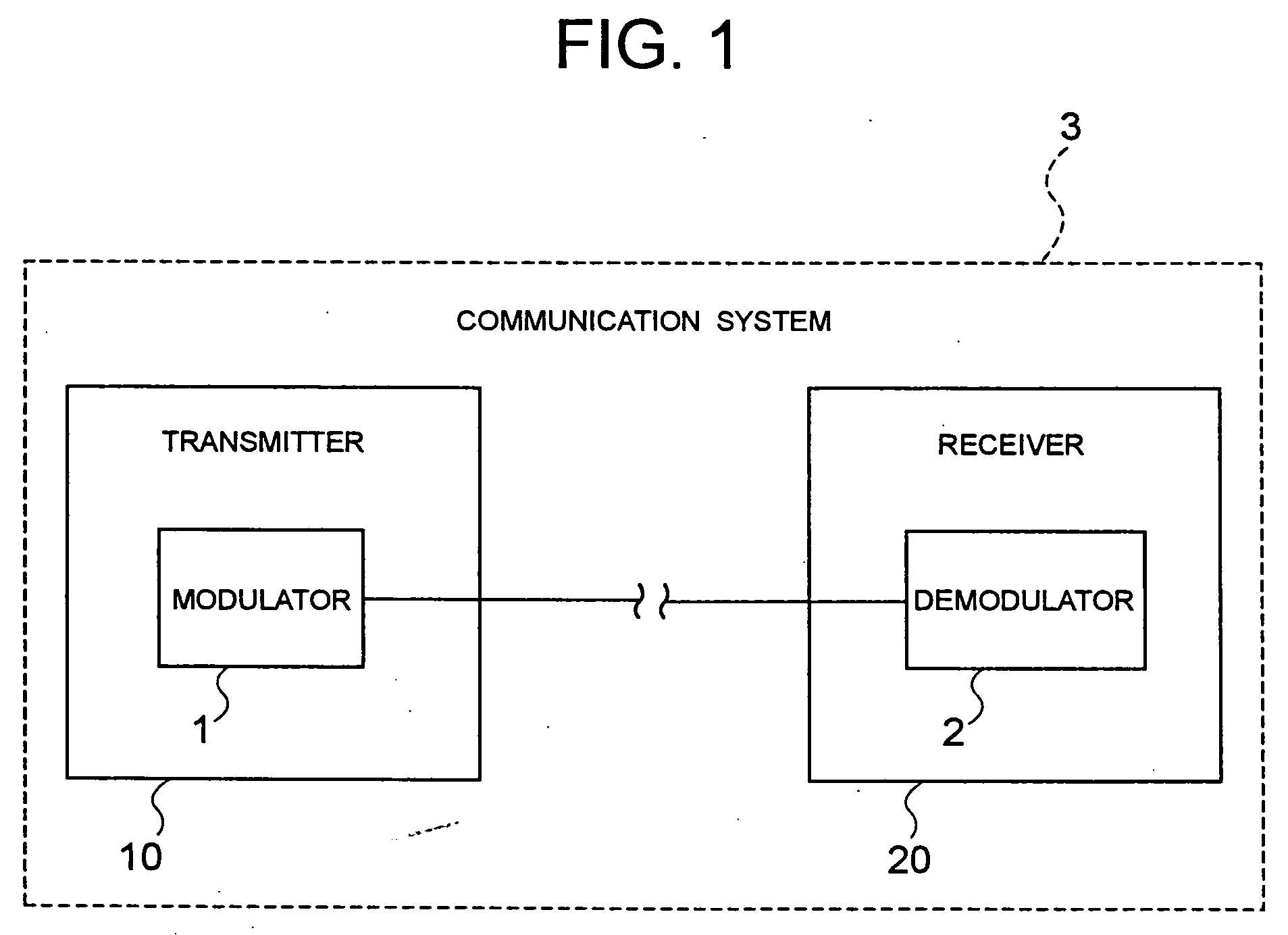
[0168] Next, the embodiment of the present invention will be described by referring to the drawings. The modulation and demodulation system (communication system) according to an embodiment of the present invention has the same configuration as well as operation as the communication system 3 according to the above-mentioned second embodiment of the present invention shown in FIG. 1.

[0169] The configuration of the modulator according to an embodiment of the present invention is the same as that of the first embodiment (FIG. 6). In FIG. 6, the modulator 1 is configured by the series parallel converter 11, binary-to-ternary converter 12, a parallel-to-serial converter (multiplexer) 13 and a senary modulation circuit 14.

[0170] The series parallel converter 11 inputs serial binary signal data of 5 bits and outputs parallel binary signal data of 3 bits and 2 bits. The binary-to-ternary converter 12 converts the parallel binary signal data of 3 bits to a ternary signal. The parallel-to-s...


PUM


Abstract

The present invention provides a modulation and demodulation system capable of minimizing a bit error rate in a six-phase phase modulation method. A senary signal phase-modulated and outputted by a modulator of a first embodiment is received and phase-modulated by a destination demodulator to a binary signal before conversion by the modulator. The modulator assigns (0, 0), (0, 1), (0, 2), (1, 2), (1, 1) and (1, 0) which are senary signals (bi, ti) to first to sixth phases respectively. The demodulator performs a conversion process from the senary signals to the binary signals, for instance, by storing transmitted senary signals and sequentially converting every senary signal of length m to binary signal of length b so as to output them. The process of the demodulator assigns the first to sixth phases as the senary signals (bi, ti) to (0, 0), (0, 1), (0, 2), (1, 2), (1, 1) and (1, 0) respectively. The modulator of a second embodiment assigns (0, 0), (0, 1), (0, 2), (1, 2), (1, 1) and (1, 0) to the first to sixth phases respectively by having the senary signals expressed as (Bi, Ti) with i=1 as a first symbol, i=2 as a second symbol, the binary signal as Bi and ternary signal as Ti. The demodulator performs a conversion process from the senary signals to the binary signals, for instance, by storing the transmitted senary signals and sequentially converting every 2 pieces of them to 5 pieces of binary signal so as to output them. The process of the demodulator assigns the first to sixth phases as the senary signals (Bi, Ti) to (0, 0), (0, 1), (0, 2), (1, 2), (1, 1) and (1, 0) respectively.

Description

BACKGROUND OF THE INVENTION [0001] 1. Field of the Invention [0002] The present invention relates to a modulation and demodulation system, a modulator, a demodulator and a phase modulation method and a phase demodulation method used therefor, and in particular, to encoding for minimizing a bit error per a symbol error in a modulation demodulation method for transmitting a binary signal of predetermined length b correspondingly to a senary phase signal of predetermined length m against a predetermined integral value N other than power of 2, and encoding for minimizing the bit error per the symbol error in the modulation and demodulation method for transmitting a binary signal of length “5” correspondingly to a senary phase signal of length “2.”[0003] 2. Description of the Prior Art [0004] Conventionally, 2n phase modulation is used with n as a positive integer in two-phase phase modulation (Binary Phase Shift Keying: BPSK), four-phase phase modulation (Quadrature Phase Shift Keying: ...

Claims


Application Information

Patent Timeline
IPC IPC(8): H04L27/20H04L27/22
CPCH04L25/4923H04L27/18H04L27/186
Inventor NODA, SEIICHIKOIKE, SHINICHI
Owner NEC CORP
Learn More