Injection molding nozzle

a technology of injection molding and nozzle, which is applied in the field of injection molding nozzle, can solve the problems of affecting the homogeneity of the supply opening, affecting the homogeneity of the product, and affecting the homogeneity of the consistency, so as to improve the homogeneity of the melt flow, and improve the mixing effect of the melt flow

Active Publication Date: 2006-04-27
OTTO MANNER INNOVATIONS
View PDF10 Cites 5 Cited by
  • Summary
  • Abstract
  • Description
  • Claims
  • Application Information

AI Technical Summary

Benefits of technology

[0011] An embodiment of the invention, wherein the delimitation of the mass flow channel becomes less restrictive toward the outlet opening has been found to be very advantageous. As the mass flow channel becomes wider toward the exit opening the melt flow expands slowly and extends all around the valve needle. This is particularly advantageous with regard to avoiding the formation of flow lines.
[0012] In another embodiment of the invention, the needle guide sleeve completely occupies at least the space remote from the outlet opening beyond the inlet opening. In this way, the flow space is delimited in the area of the inlet opening in a simple manner as no melt can enter the area in which the needle guide sleeve fully occupies the mass flow channels. In addition, a space delimitation can be established in this way in a very simple and inexpensive way.
[0013] An embodiment of the invention, wherein the needle guide sleeve is provided at its surface with recesses which form channels with the wall of the mass flow channel has been found to be particularly advantageous. The recesses or, respectively, channels define the path for the melt flow in a particularly simple way. In the areas where the needle guide sleeve has no recesses, the needle guide sleeve completely fills the mass flow channel so that the mass flow channel space around the inlet opening can be limited in providing no recesses or flow passages in the needle guide sleeve in the respective area.
[0014] In the last mentioned embodiment, it is very advantageous if the recesses extend thread-like around the needle guide sleeve. It is particularly advantageous if at least two recesses are provided which are in the form of a single-pass right, or respectively, left hand thread. In this way, one twist while the other channel extends once around the needle guide sleeve with a right twist, such that the two channels intersect at the side of the needle guide sleeve opposite the inlet opening. With the channels intersecting the mixing action is increased and consequently the homogeneity of the melt flow is improved.
[0015] The mixing of the melt flow however may be substantially increased in that the needle guide sleeve is provided with a plurality of parallel recesses. It is then very advantageous if the recesses or, respectively, the respective channels start out each in the recesses or, respectively, channels, which extend on the surface of the needle guide sleeve like a single-pass left hand or, respectively, right hand thread. With the multitude of the parallel-extending recesses also a plurality of intersections are formed whereby a very good mixing and consequently homogeneity of the melt is obtained. In this way, the formation of flow lines is almost completely avoided.
[0016] An embodiment of the invention wherein the cross-section of the recesses increases with increasing distance from the inlet opening is also very advantageous. In this way, advantageously about the same melt mass flow passes through the area of the mass flow channel opposite the inlet opening as through the area adjacent the inlet opening. The greater length of the melt travel passing through the channel extending to the side remote from the inlet opening is compensated for by an increase in the cross-section of the recesses. Also, in this way, the homogeneity of the melt is increased and a uniform melt flow front is obtained.

Problems solved by technology

However, the homogeneous consistency which may still be present at the supply opening may be disturbed by the valve needle disposed in the mass flow channel.
Such flow lines are very objectionable since the flow lines are optically apparent in the injection-molded component and may result in discarding the product.
Furthermore, in remote areas of the mass flow channel, melt material may be retained in the known hot channel nozzles and re-entrained into the melt flow at a later time, whereby the homogeneous consistency is also much disturbed.
The problem encountered with a side admission opening for the melt however cannot be eliminated by the known mixing element.

Method used


Image

  • Injection molding nozzle
  • Injection molding nozzle
  • Injection molding nozzle

Examples


Embodiment Construction

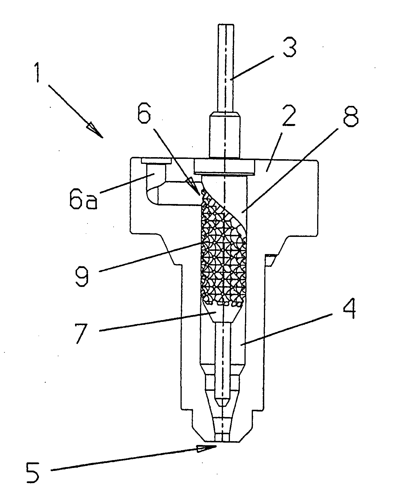
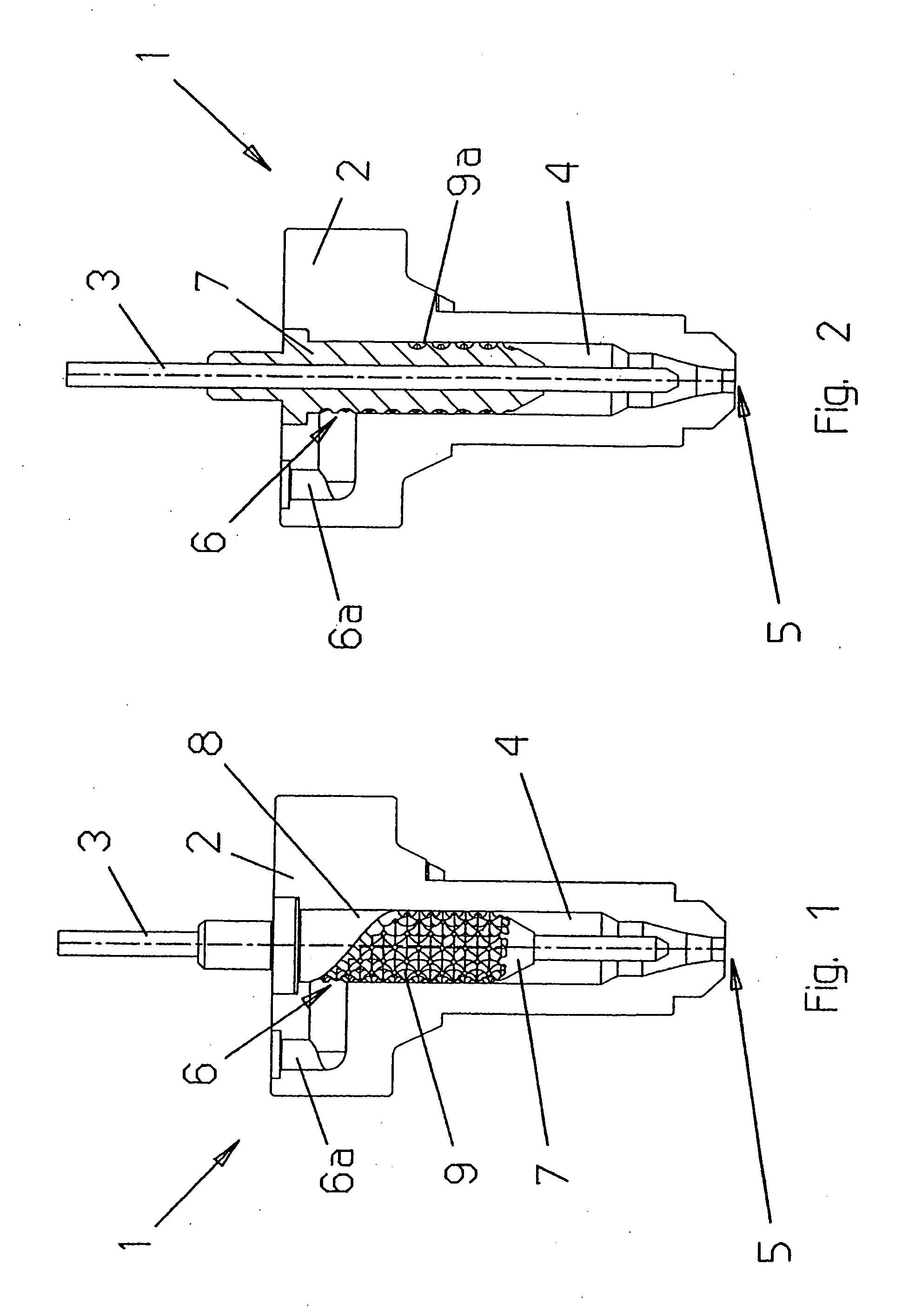
[0024] As apparent from FIGS. 1 and 2, a hot channel nozzle 1 comprises a nozzle body 2, through which a melt mass flow channel 4 extends. The mass flow channel 4 has at one end thereof an inlet opening 6 by way of which a plastic material melt can be supplied to the mass flow channel 4 via a supply passage 6a formed into the nozzle body 2. At the other end, the mass flow channel 4 has a nozzle-shaped outlet opening 5. The nozzle outlet opening 5 or an adjacent connecting opening of the injection molding tool which is not shown can be opened or closed by a valve needle 3, which extends axially through the mass flow channel 4.

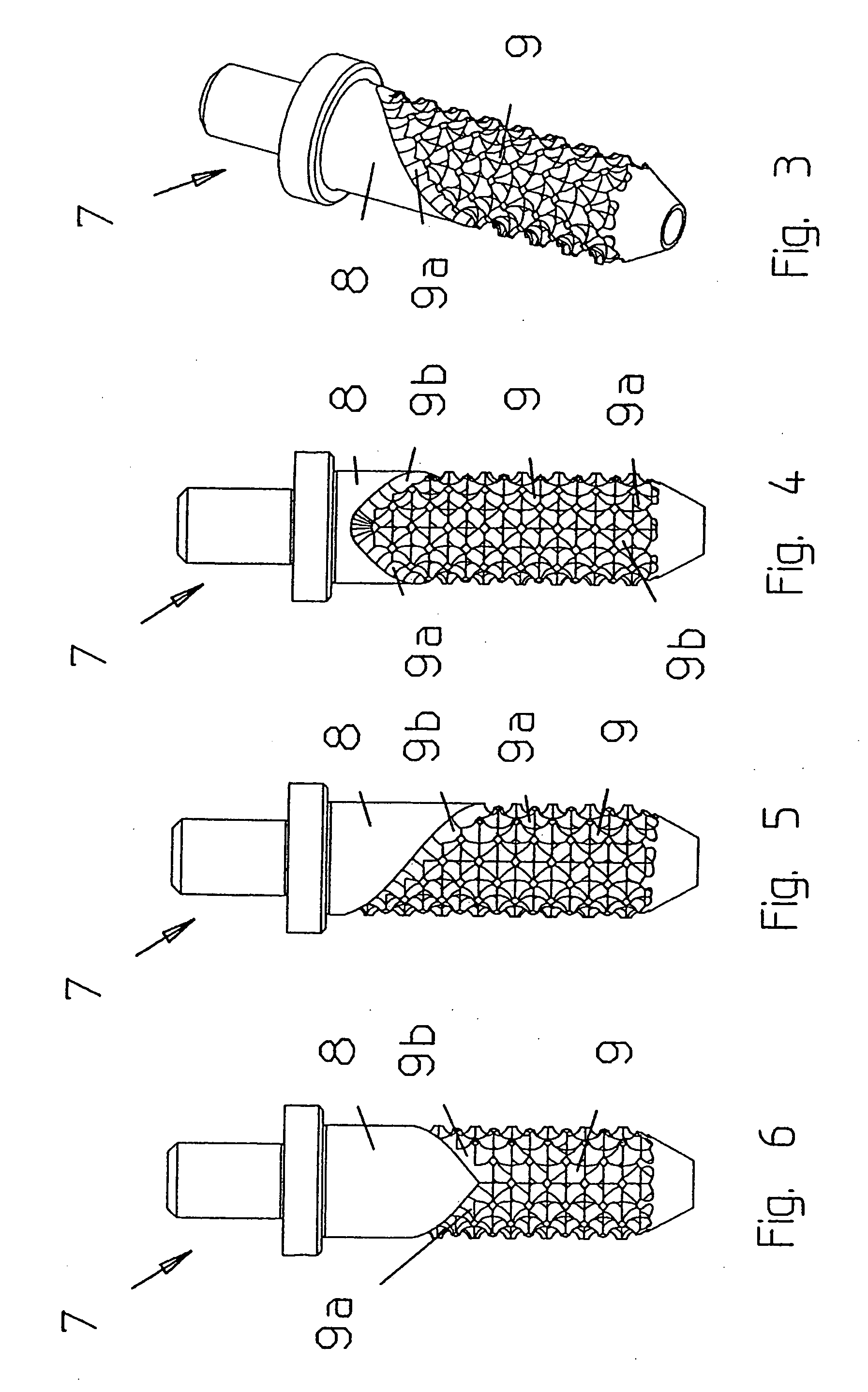
[0025] At the end of the mass flow channel 4 opposite the nozzle outlet opening 5, a needle guide sleeve 7 is arranged in the mass flow channel 4 and a valve needle 3 extends through the needle guide sleeve 7 in which the valve needle 3 is axially movably and sealingly supported. The mass flow channel 4 is sealingly closed by the needle guide sleeve 7 at its on...


PUM

PropertyMeasurementUnit
areaaaaaaaaaaa
mass flowaaaaaaaaaa
massaaaaaaaaaa

Abstract

In a hot channel injection molding nozzle comprising a nozzle body including a mass flow channel for a melt to be injected into a mold, wherein the nozzle body has a nozzle outlet opening at one end and an inlet opening disposed at one side of the other end of the nozzle body and a valve needle extending through the nozzle body to the outlet opening for blocking the melt flow, a valve needle guide sleeve is disposed in the nozzle body so as to delimit the mass flow channel in the area of the inlet opening with the valve needle extending through the guide sleeve.

Description

BACKGROUND OF THE INVENTION [0001] The invention relates to an injection molding nozzle for hot channel injection molds, comprising a nozzle body which has a mass flow channel for a melt provided at one end with a nozzle discharge opening and, at its other end, with a supply opening arranged at the side of the nozzle body through which a valve needle extends for controlling the discharge of the melt from the nozzle opening. [0002] Such a hot channel nozzle is known, for example, from DE 199 50 273 C1. In the known hot channel nozzle, which is generally installed in an injection molding tool, molten plastic is conducted via channels arranged in the injection molding tool by way of the side supply openings to the mass flow channel. By way of the mass flow channel, which is generally filled with melt, the melt reaches the nozzle discharge opening. When the valve needle opens the nozzle discharge opening, melt can flow into the mold disposed adjacent the nozzle discharge opening. When t...

Claims


Application Information

Patent Timeline
Patent Type & Authority Applications(United States)
IPC IPC(8): B29C47/96B29C48/96
CPCB29C45/2806B29C45/30B29C2045/2889B29C2045/308
Inventor SPULLER, SWEN
Owner OTTO MANNER INNOVATIONS
Why Eureka
Try Eureka