Cutting apparatus employing high pressure fluid jet

a cutting apparatus and high pressure technology, applied in the direction of shearing apparatus, metal-working apparatus, shearing tools, etc., can solve the problems of reducing the service life of the cutting apparatus, so as to achieve the effect of suitable machining energy

Inactive Publication Date: 2006-05-04
HORI SHIMAKI +2
View PDF3 Cites 0 Cited by
  • Summary
  • Abstract
  • Description
  • Claims
  • Application Information

AI Technical Summary

Benefits of technology

[0015] In view of the above-described problems observed in the prior art, an object of the present invention is to provide a cutting method and apparatus employing a high pressure fluid jet, which can provide a suit

Problems solved by technology

However, in a case where required machining energy (i.e., cutting energy) is achieved by adjusting the discharge pressure of the super high pressure pump in the cutting apparatus employing the high pressure fluid jet while using the same super high pressure fluid pipeline, the super high pressure fluid pipeline becomes fatigued, and thus, its lifetime may be markedly shortened since the super high pressure fluid pipeline is expande

Method used


Image

  • Cutting apparatus employing high pressure fluid jet
  • Cutting apparatus employing high pressure fluid jet
  • Cutting apparatus employing high pressure fluid jet

Examples


Embodiment Construction

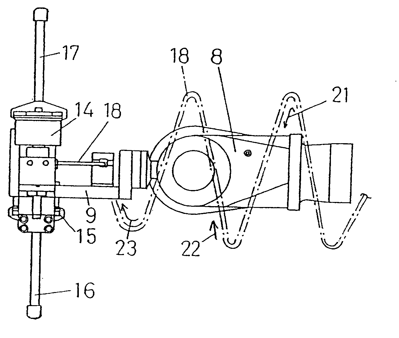
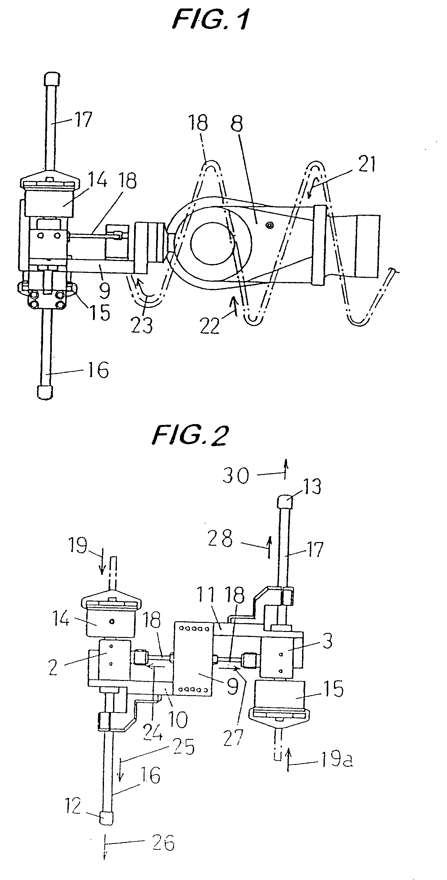
[0038] A preferred embodiment according to the present invention will be described below in reference to FIGS. 1 to 3(b).

[0039] As shown in FIG. 1, one end of a valve frame 9 is fixed at a tip of a robot hand 8 of a revolute robot, not shown. To another end of the valve frame 9 are fixed switch valves 2 and 3 via fixing arms 10 and 11, respectively, as shown in FIG. 2. The switch valves 2 and 3 are connected at one end thereof to actuators 14 and 15, while at another end thereof to one end of nozzle tubes 16 and 17, respectively. A pore diameter of each of the nozzle tubes 16 and 17 on a side connected to the switch valves 2 and 3 is formed of a normal size.

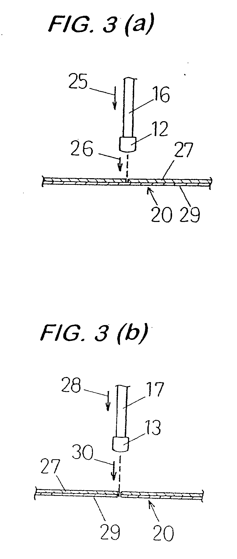
[0040] In contrast, a nozzle 12 provided with an orifice having a diameter of 3 / 1000 inch, and a nozzle 13 provided with an orifice having a diameter of 8 / 1000 inch, are fixed at another end of the nozzle tubes 16 and 17, respectively.

[0041] To the switch valves 2 and 3 are connected a super high pressure fluid pipeline 18 con...


PUM

PropertyMeasurementUnit
Pressureaaaaaaaaaa

Abstract

Provided is a cutting apparatus employing a high pressure fluid jet including a super high pressure pump for increasing pressure of a fluid so as to form a super high pressure fluid, a super high pressure fluid nozzle having an orifice for ejecting the super high pressure fluid so as to form a high rate ejected flow, a super high pressure fluid pipeline for connecting the super high pressure pump and the super high pressure fluid nozzle to each other, and a switch valve interposed between the super high pressure fluid nozzle and the super high pressure fluid pipeline so as to connect or disconnect supply of the super high pressure fluid; wherein the super high pressure fluid nozzle is provided in plurality, in which diameters of the orifices provided with nozzles are different from each other, and supply of the super high pressure fluid from the super high pressure fluid pipeline to the super high pressure fluid nozzle is changed from one nozzle to another nozzle of the plural super high pressure fluid nozzles.

Description

BACKGROUND OF THE INVENTION [0001] 1. Field of the Invention [0002] The present invention relates to a cutting method and apparatus employing a high pressure fluid jet, in which a high rate ejection flow is formed by ejecting a super high pressure fluid from a nozzle, thus achieving cutting or the like by allowing this ejection flow to collide with a workpiece. [0003] More particularly, the present invention relates to a cutting method and apparatus employing a high pressure fluid jet suitable for cutting a workpiece made of a plurality of members laminated one on another, with each member having a different quality of material. [0004] 2. Description of the Related Art [0005] There has been a conventionally known cutting apparatus employing a high pressure fluid jet. This cutting apparatus includes a super high pressure pump for increasing pressure of a fluid so as to form a super high pressure fluid, a super high pressure fluid nozzle having a very small pore called an orifice for ...

Claims


Application Information

Patent Timeline
IPC IPC(8): B26F3/00
CPCB23D35/008B26D11/00B26F3/004Y10T83/364Y10T83/0591Y10T83/04
Inventor HORI, SHIMAKIOBA, TATSUYAURASAKI, YOSHIAKI
Owner HORI SHIMAKI
Why Eureka
Try Eureka