Regenerative brake device and motor-assisted vehicle provided with the same

a technology of regenerative brakes and motors, which is applied in the direction of braking systems, propulsion by batteries/cells, cycles, etc., can solve the problems of user pressing the brake lever even harder, waste of useful energy, and inability to provide a linear adjustment of regenerative braking force, etc., to achieve suitable energy recapture, reduce the loss of manual brake energy, and improve the travel distance of electric assist vehicles with a single battery charge

Active Publication Date: 2017-02-21
TAIYO YUDEN KK
View PDF59 Cites 4 Cited by
  • Summary
  • Abstract
  • Description
  • Claims
  • Application Information

AI Technical Summary

Benefits of technology

[0019]Effects of the present invention are as follows: according to various embodiments of the present invention, the operation amount of the brake lever is detected, and before the manual brake is engaged, a regenerative brake is generated in accordance with the operation amount, i.e., grip strength. This makes it possible to provide a braking force desired by the user of the electric assist vehicle without making him / her feel a gap between the operation amount and the actual braking action. Also, because the regenerative brake is applied before heat is generated due to the manual brake, a loss in the energy caused by the manual brake can be reduced, thereby achieving a suitable energy recapture. As a result, a travel distance of the electric assist vehicle with a single battery charge can be improved. In other words, because the frequency of removing the battery from the vehicle for charging can be reduced, the battery life can be extended. Further, because the function of the manual brake is not sacrificed, safety can be assured, and the regenerative brake device can be mounted on existing electric assist vehicles.

Problems solved by technology

However, this only makes it possible to adjust the force in two ways, strong or weak, and this does not provide a linear adjustment of the regenerative braking force in proportion to the operation amount of the brake lever.
When the regenerative braking force is insufficient, a braking force, i.e., a force to stop or slow down a vehicle, becomes insufficient, which makes the user squeeze the brake lever even harder.
This actuates a braking force of the manual brake, causing the useful energy to be wasted in the form of heat loss due to the friction between the brake pads and the rim.
On the other hand, when the regenerative braking force is excessive, the brake is actuated abruptly when the switch is turned on, and this makes it difficult for users to operate the brake comfortably until they get used to it.

Method used


Image

  • Regenerative brake device and motor-assisted vehicle provided with the same
  • Regenerative brake device and motor-assisted vehicle provided with the same
  • Regenerative brake device and motor-assisted vehicle provided with the same

Examples


embodiment 1

[0030

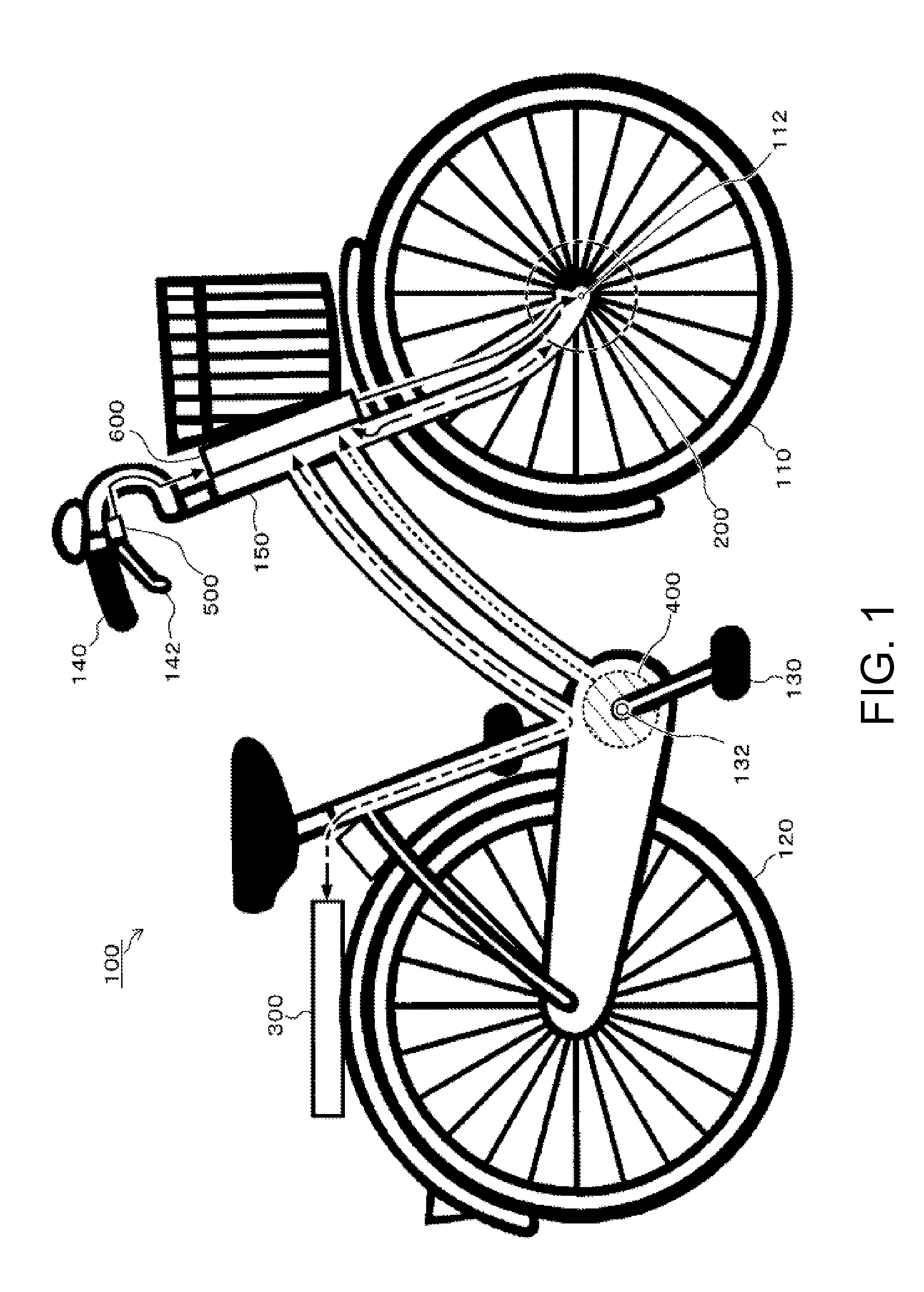
[0031]First, Embodiment 1 of the present invention will be explained with reference to FIGS. 1 to 5. FIG. 1 shows an overall configuration of a vehicle of this embodiment. This figure shows an example where the present invention is employed in an electric assist bicycle. In the figure, a motor 200 is provided around a hub 112 of a front wheel 110 of an electric assist bicycle 100. A battery (secondary cell) 300 is disposed near a rack of a rear wheel 120. A torque sensor 400 is disposed around a crankshaft 132 of pedals 130, and a brake sensor 500 is disposed near a brake lever 142 of a handlebar 140. Further, a handle stem 150 has a controller 600 on a side facing a front basket. The motor 200, the battery 300, the torque sensor 400, and the brake sensor 500 are connected to the controller 600 by wiring lines arranged along pipes and a fork. An alarm 700 and a brake lever operation amount sensor 800 will be explained in embodiments below.

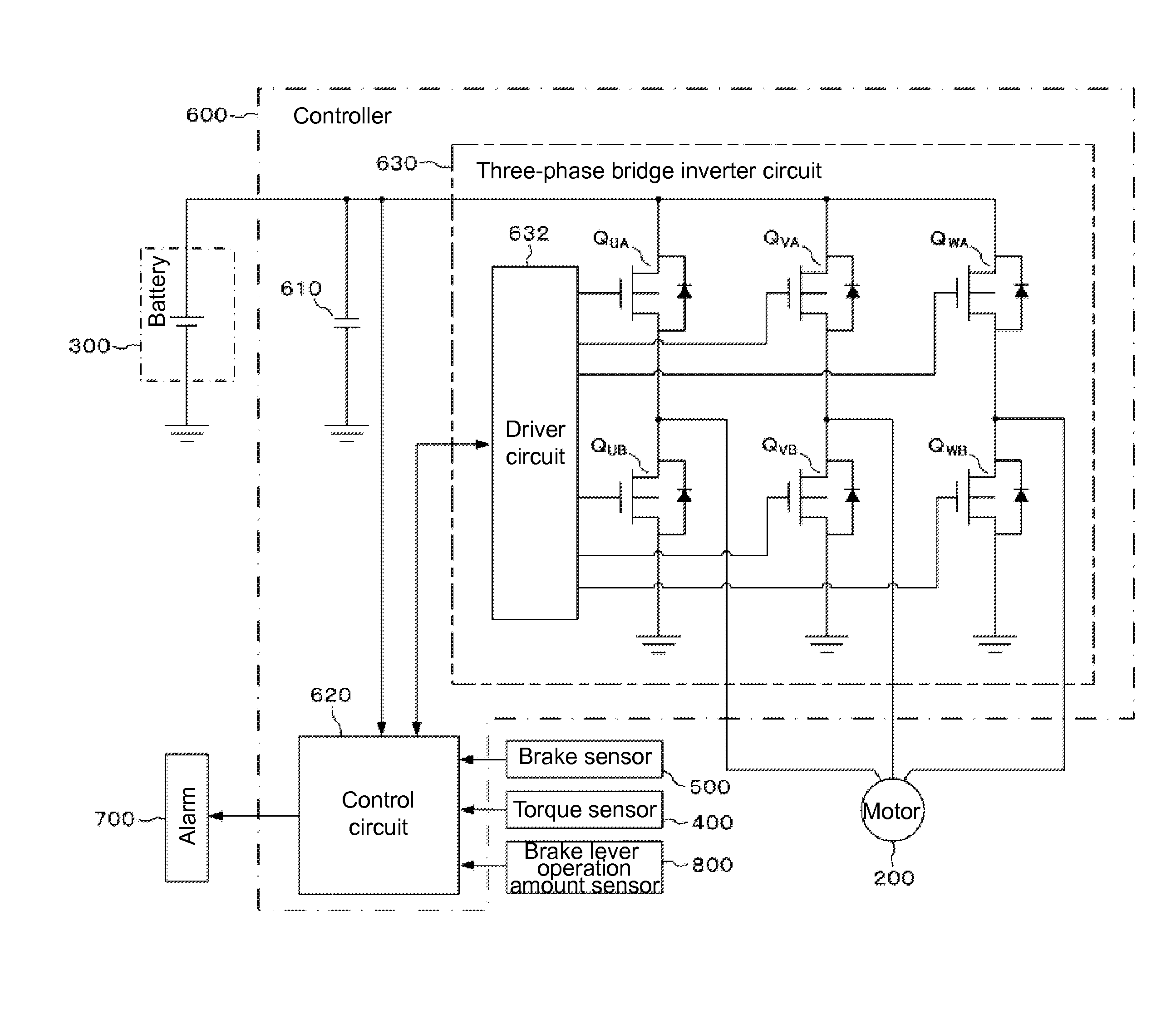
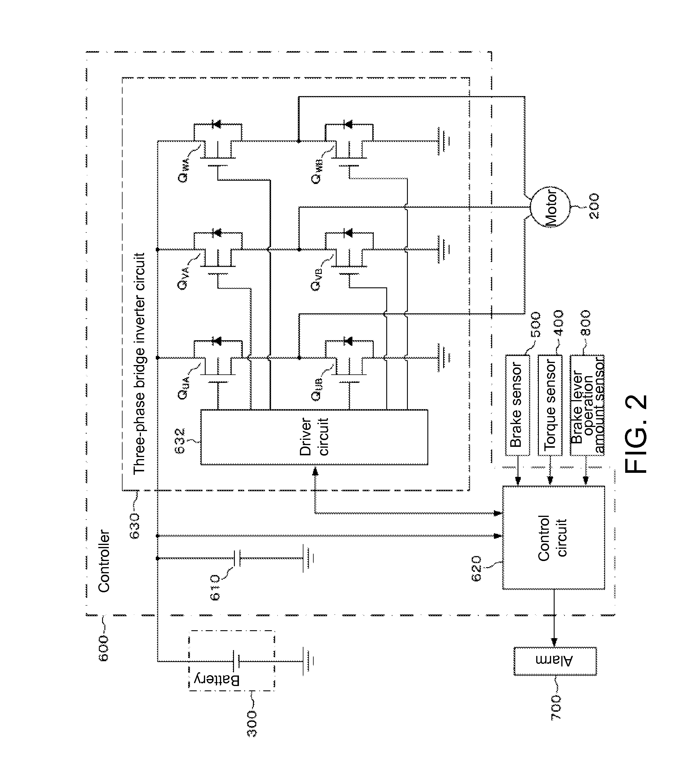
[0032]FIG. 2 shows an example of an ele...

embodiment 2

[0051

[0052]Next, with reference to FIG. 6, Embodiment 2 of the present invention will be explained. In the regions BA and BP shown in FIG. 5(C), the regenerative brake is applied linearly. In this specification, these regions where the manual brake is not actuated even when the user operates the brake lever 142 are referred to as play stages. If the region BQ where the manual brake is activated is to be increased to provide an adequate manual braking action for safety, the play stages BA and BP would need to be reduced. In such a case, the linear control of the regenerative duty ratio would need to be conducted by detecting a change in the brake lever operation amount in a smaller operating range in accordance with data values that have been measured in advance similar to the conversion graph shown in FIG. 5(B). This would create a need to use a high-accuracy, high-capability and expensive sensor as the brake sensor 500.

[0053]Also, even if the adequate play stages BA and BP are prov...

embodiment 3

[0058

[0059]Next, Embodiment 3 of the present invention will be explained. In this embodiment, as shown in FIG. 2, the alarm 700 is connected to the control circuit 620. As the alarm 700, an appropriate device, such as a light-emitting device employing a light-emitting diode or the like, or a sounding device employing a piezoelectric element, a speaker, or the like, can be used. When the manual brake is actuated by the increased displacement of the brake wire 144, and the actuation thereof is recognized through the detection signal from the brake sensor 500, the control circuit 620 drives the alarm 700 so as to alert the user of the actuation. Referring to FIG. 5(B), the alarm 700 is activated when the brake sensor output signal that exceeds the signal at the manual brake application point PQ is detected. The manual brake application point PQ can be determined by storing the brake output value at the point PQ in FIG. 5(B) in advance in the memory of the control circuit 620 in FIG. 2....


PUM


Abstract

A regenerative brake device for a vehicle includes a manual brake configured to apply a brake to a wheel of the vehicle by a manual operation of a brake lever; a motor configured to be coupled to a wheel of the vehicle, the motor being driven by a power from a battery, and also alternatively acting as a regenerative brake that charges the battery with an electromotive force of the motor; a brake sensor that detects a manual brake application point at which the manual brake is actuated from an operation amount of the brake lever; and a power control unit that performs regenerative power control for charging the battery with the electromotive force of the motor based on an output signal from the brake sensor so that the regenerative brake is generated in accordance with the operation amount of the brake lever.

Description

[0001]This application is a continuation of PCT International Application No. PCT / JP2010 / 066342 designating the United States, filed Sep. 22, 2010, which claims the benefit of Japanese Application No. 2009-231908, filed in Japan on Oct. 5, 2009. Both applications are hereby incorporated by reference in their entireties.[0002]The present application also hereby incorporates by reference PCT International Application No. PCT / JP2010 / 067487, filed Oct. 5, 2010, which claims the benefit of Japanese Application No. 2009-231845, filed in Japan on Oct. 5, 2009, and Japanese Application No. 2010-084081, filed in Japan on Mar. 31, 2010 in their entireties.TECHNICAL FIELD[0003]The present invention relates to a regenerative brake device, and more particularly, to a regenerative brake device that is suitably used for a vehicle that has electric assist power in addition to human power, and an electric assist vehicle provided with the same.BACKGROUND ART[0004]Recently, from ecological and health ...

Claims


Application Information

Patent Timeline
Patent Type & Authority Patents(United States)
IPC IPC(8): B60T8/64B60T1/10B62M6/45B60L7/14B60W10/08B60W10/184B60L11/00B60L11/18B60L7/26B60T13/74B60W30/18
CPCB60T1/10B60L7/14B60L7/26B60L11/007B60L11/1801B60L11/1803B60L11/1877B60W10/08B60W10/184B62M6/45B60L2200/12B60L2250/10B60L2250/24B60T2270/604B60W30/18127B60W2300/36B60W2540/12B60Y2200/12Y02T10/7005Y02T10/705B60T8/261B60L50/20B60L50/51B60L50/53B60L50/66Y02T10/70
Inventor HOSAKA, YASUOASANUMA, KAZUOKAGAWA, TOSHIYUKI
Owner TAIYO YUDEN KK
Why Eureka
Try Eureka