Process for feeding pulp into a blow tank or storage tank

a technology applied in the direction of digesters, machine wet ends, textiles and paper, etc., can solve the problems of remarkable amount of pumping energy loss, waste of energy, and energy consumption of blowing and storage tanks

Inactive Publication Date: 2006-05-04
SULZER MANAGEMENT AG
View PDF3 Cites 2 Cited by
  • Summary
  • Abstract
  • Description
  • Claims
  • Application Information

AI Technical Summary

Benefits of technology

[0012] Said problems are suggested to be solved by an arrangement where part of the pulp is discharged into the tank via its upper part and part of the pulp through the lower part of the tank. Further, the pulp discharged via the upper part of the tank is in the upper part of the tank distributed evenly onto the whole cross section of the tank, whereby even the pulp discharged from the upper part of the tank is not capable of penetrating deep into the pulp existing in the tank, but stays on the surface of the pulp, thus ensuring that the consistency of the pulp remains uniform at various locations in the storage tank and that the pulp flows evenly at a relatively uniform consistency downwards to the mixing zone.

Problems solved by technology

The operating model described above solves a third problem, too, viz. a disadvantage related to the energy consumption of the filling of blow and storage tanks.
It has namely been noticed that especially when the tanks are filled through an inlet opening arranged at the upper end of the tank only, remarkable amount of pumping energy is lost due to great fluctuations in the pulp level in the tank.
Pumping the pulp to the altitude of the upper end of the tank and letting it drop from there to the bottom of the tank is mere waste of energy.

Method used


Image

  • Process for feeding pulp into a blow tank or storage tank
  • Process for feeding pulp into a blow tank or storage tank
  • Process for feeding pulp into a blow tank or storage tank

Examples


Embodiment Construction

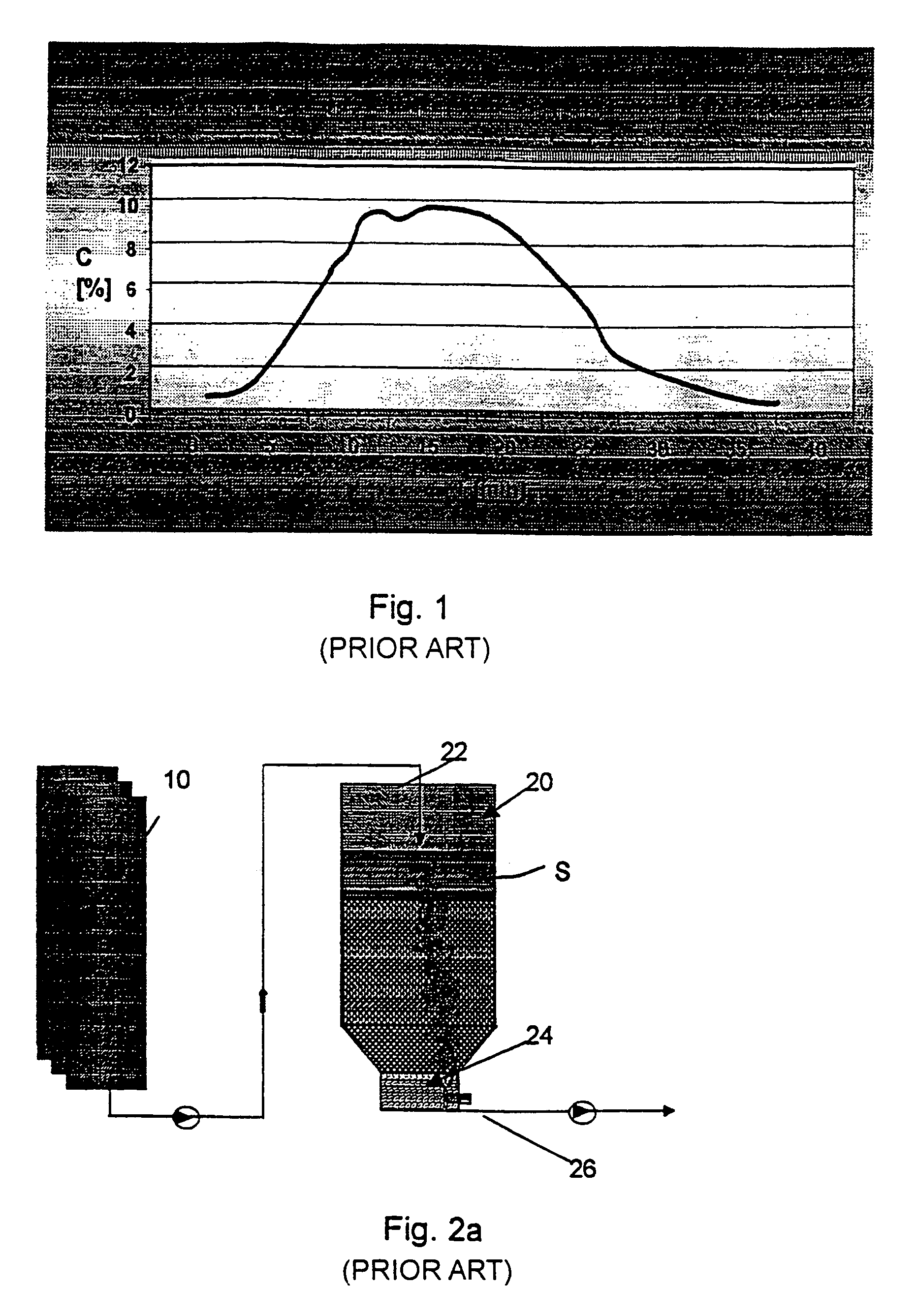
[0020]FIG. 1 illustrates the consistency variation of the pulp during the blow of one digester. As already stated, the consistency is low both in the beginning and in the end of the discharge. In about the middle stage of the blow the consistency of the pulp may be in the order of about ten percent. The time interval between two blows is about 20-40 minutes, depending on the size and number of digesters. In our studies we have noticed that said interval in the order of about half an hour is sufficient to cause the pulp on the surface in the blow tank to filtrate, or thicken, whereby a relatively solid, and continuously solidifying, pulp cake is formed onto the surface of the pulp already existing in the tank. One has to notice about the described figure that it is only an example of a batch digester and a blow as run by one operator. That is, each mill and each operator there and even each digester may produce different consistency profiles as a function of discharge time.

[0021]FIG...


PUM

PropertyMeasurementUnit
pressureaaaaaaaaaa
period of timeaaaaaaaaaa
hydrostatic pressureaaaaaaaaaa

Abstract

A method and apparatus for treating pulp in connection with a blow tank or a storage tank. The pulp is discharged from a batch digester and fed either to the upper or the lower part of a blow tank, depending on the consistency of the pulp being discharged from the digester.

Description

RELATED APPLICATION [0001] This application is a divisional application of U.S. patent application Ser. No. 09 / 913,331, filed Oct. 11, 2001, which is a U.S. National Phase Application of International PCT Application PCT / FI00 / 00067 filed Feb. 2, 2000 (as amended on February, 2001), which claims priority to Finnish Patent Application No. 990290 filed Feb. 15, 1999, the entire contents of each of these applications are incorporated by reference herein.BACKGROUND OF THE INVENTION [0002] The present invention relates to a method and apparatus for treating pulp. A problem resulting in the development of the method and apparatus according to the invention becomes especially obvious during the feed and discharge of blow tanks used in connection with batch digesters. Thus, putting it more precisely, the method and apparatus according to the invention relate to the filling and discharging of various pulp tanks and storage containers. [0003] It is known from prior art that a so-called blow ta...

Claims


Application Information

Patent Timeline
Patent Type & Authority Applications(United States)
IPC IPC(8): D21C7/06D21C7/08D21C9/00D21D5/28
CPCD21C7/08D21C9/007D21D5/28
Inventor HEIKKILA, MARTTIKOVASIN, KARIROBERG, KARL-ERIKTOUKONUMMI, OLAVI
Owner SULZER MANAGEMENT AG
Why Eureka
Try Eureka