Formation dip geo-steering method

a geo-steering and dip technology, applied in the direction of surveying, directional drilling, borehole/well accessories, etc., can solve the problems of several problems in all these techniques

Active Publication Date: 2006-05-04
WILLIAMS DANNY T
View PDF7 Cites 65 Cited by
  • Summary
  • Abstract
  • Description
  • Claims
  • Application Information

AI Technical Summary

Benefits of technology

[0010] An advantage of the present invention includes use of logs from offset wells such as gamma ray, resistivity, density neutron, sonic or acoustic, and surface and subsurface seismic. Another advantage is that the present invention will use data from these logs and other surface and down hole data to calculate a dip for a very thin target zone. Yet another advantage is that during actual drilling, the method herein disclosed will produce a target window (top and bottom) and extrapolate this window ahead of the projected well path so an operator can keep the drill bit within the target zone identified by the ifdip and target window.
[0011] A feature of the present invention is that the method uses real time drilling and logging data and historical data to recalculate the instantaneous dip of the target window as to its correlation of the real time logging data versus the offset wells data in relationship to the TSP of the drill bit within the target window. Another feature is that the method will then produce a new target window (top and bottom) and wherein this new window is extrapolated outward. Yet another feature is that this new window will be revised based on actual data acquired during drilling such as, but not limited to, the real time gamma ray indicating bed boundaries. Yet another feature is that the projection window is controlled by the top of the formation of interest as well as the bottom of the formation of interest. In other words, a new window will be extrapolated based on real time information adjusting the top and / or bottom of the formation of interest as it relates to the TSP of the drill bit within that window, through the correlation of the real time logging and drilling data to the offset well data.

Problems solved by technology

However, all these techniques suffer from several problems.

Method used


Image

  • Formation dip geo-steering method
  • Formation dip geo-steering method
  • Formation dip geo-steering method

Examples


Embodiment Construction

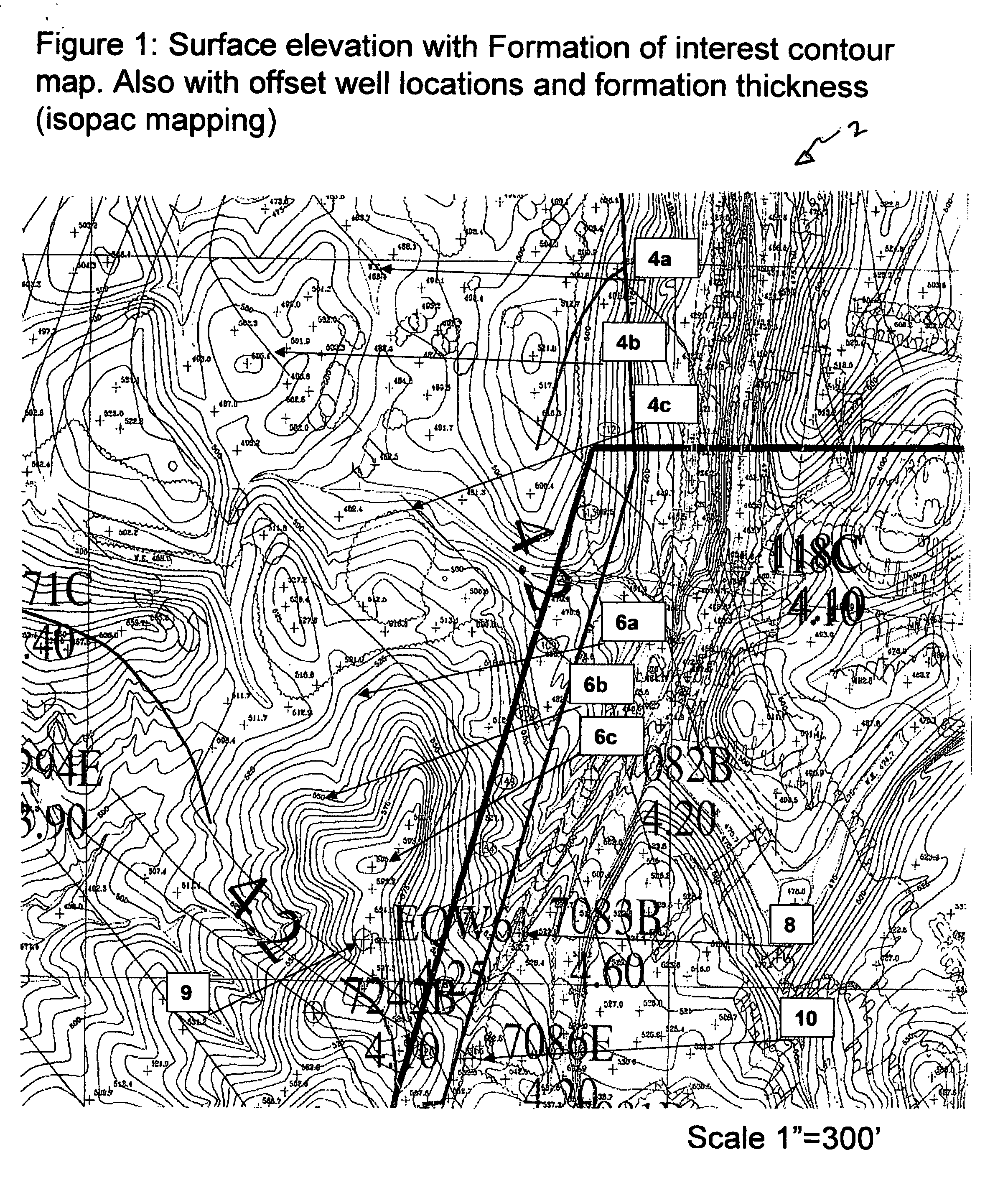
[0021] Referring now to FIG. 1, a surface elevation with formation of interest contour map 2 with offset well locations will now be described. As seen in FIG. 1, the subsurface top of target formation of interest (FOI) contour lines (see generally 4a, 4b, 4c) are shown. Also shown in FIG. 1 is the surface elevation lines (see generally 6a, 6b, 6c). FIG. 1 also depicts the offset well location 8, 9 and 10, and as seen on the map, these offset well locations contain the target formation window thickness as intersected by those offset wells.

[0022] As understood by those of ordinary skill in the art, map 2 is generated using a plurality of tools such as logs, production data, pressure buildup data, and core data from offset wells 8, 9 and 10. Geologist may also use data from more distant wells. Additionally, seismic data can be used in order to help in generating map 2.

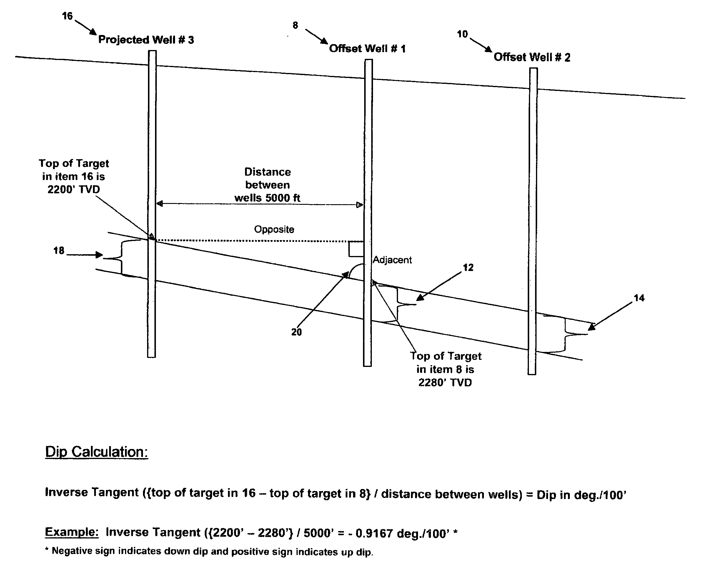
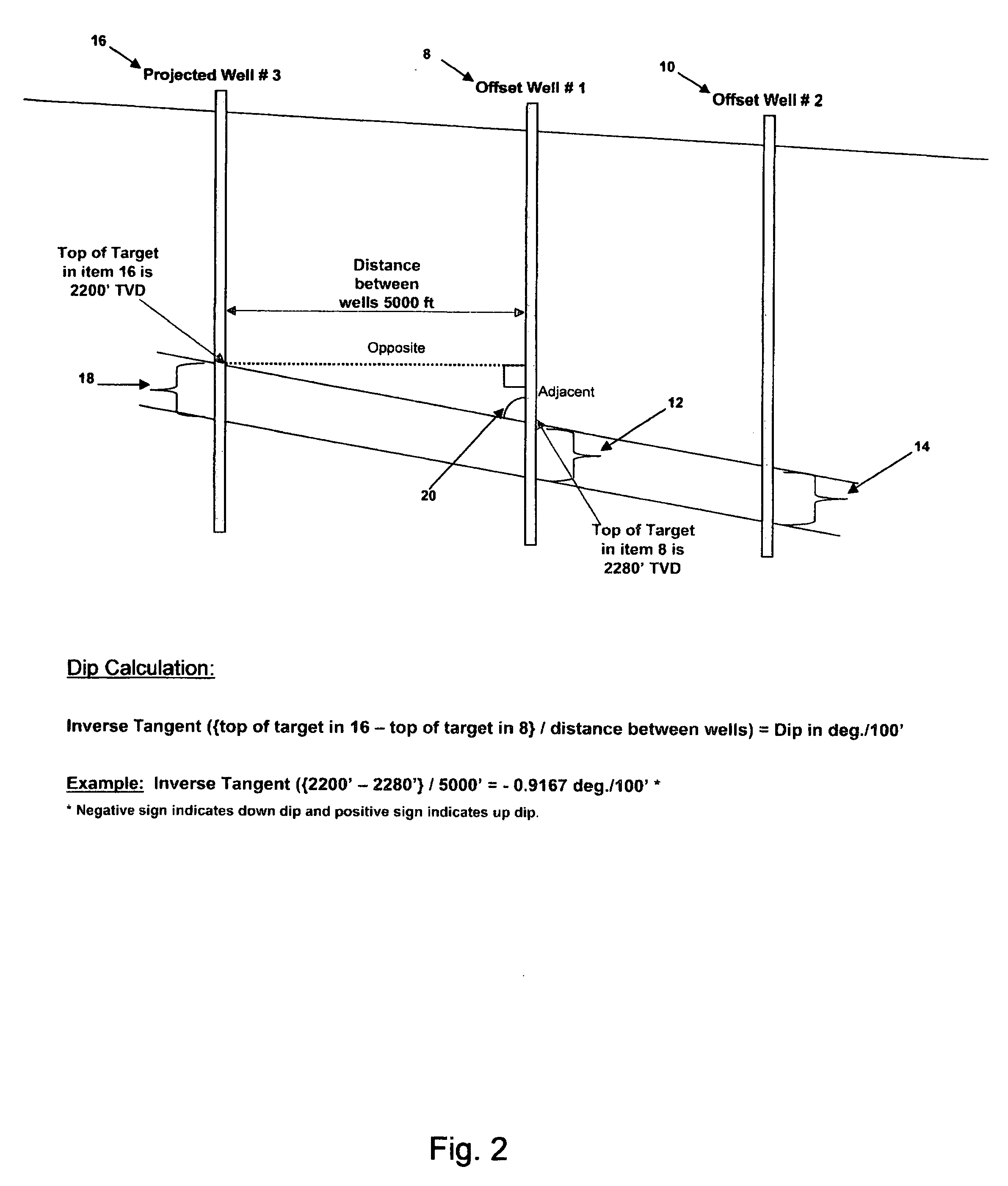
[0023] Referring now to FIG. 2, a partial cross-sectional geological view of two offset wells and a proposed well 16 ...


PUM


Abstract

A method of drilling a well. The method includes calculating an estimated formation dip angle, wherein said estimated formation dip angle being based on offset well data, seismic data, core data, pressure data. Next, the method includes drilling a well with a logging while drilling means so that real time logging data is generated along with drilling data and calculating an instantaneous formation dip angle. Next, real time logging data is obtained and a target formation window is projected ahead of the well path that includes a top of formation and a bottom formation. The method includes monitoring the real time logging and drilling data and drilling the well through the target formation window. The method further includes changing the estimated instantaneous formation dip based on the obtained data and adjusting the target formation top and bottom window.

Description

BACKGROUND OF THE INVENTION [0001] This invention relates to a method of steering a drill bit. More specifically, but not by way of limitation, this invention relates to a method of geo-steering a bit while drilling directional and horizontal wells. [0002] In the exploration, drilling and production of hydrocarbons, it becomes necessary to drill directional and horizontal wells. As those of ordinary skill in the art appreciate, directional and horizontal wells can increase the production rates of reservoirs. Hence, the industry has seen a significant increase in the number of directional and horizontal wells drilled. Additionally, as the search for hydrocarbons continues, operators have increasingly been targeting thin beds and / or seams with high to very low permeability. The industry has also been targeting unconventional hydrocarbon reservoirs such as tight sands, shales, and coal. [0003] Traditionally, these thin bed reservoirs, coal seams, shales and sands may range from less th...

Claims


Application Information

Patent Timeline
Patent Type & Authority Applications(United States)
IPC IPC(8): E21B25/16E21B47/02
CPCE21B7/04
Inventor WILLIAMS, DANNY T.
Owner WILLIAMS DANNY T
Why Eureka
Try Eureka