Patterned illumination method and apparatus for machine vision systems

a machine vision and apparatus technology, applied in mechanical equipment, counting objects on conveyors, instruments, etc., can solve the problems of unfavorable performance of machine vision systems in these classes of defects, unfavorable inspection (automatic or otherwise), and unfavorable inspection (automatic or otherwise)

Inactive Publication Date: 2006-05-04
PRESSCO TECH INC
View PDF20 Cites 15 Cited by
  • Summary
  • Abstract
  • Description
  • Claims
  • Application Information

AI Technical Summary

Benefits of technology

[0023] An advantage of the present invention is that it provides directional lighting across the full surface of highly specular, 3-dimensional parts.
[0024] Another advantage of the present invention is that it produces controlled hot-spot image artifacts that allow high-speed automated inspections to take place.
[0025] Yet another advantage of the present invention is that it allows highly specular, 3-dimensional parts to be inspected for the presence of critical surface flaws

Problems solved by technology

On these classes of parts, the directional lighting associated with ringlight illumination causes uneven returns from the part under inspection.
In addition to getting scatter-induced reflections at defect locations such as scratches and pits (which are preferred), intense image artifacts are also generated at all locations wherein the local surface orientation (due to normal part contours) allow light emitted by the ringlight source to be specularly-reflec

Method used


Image

  • Patterned illumination method and apparatus for machine vision systems
  • Patterned illumination method and apparatus for machine vision systems
  • Patterned illumination method and apparatus for machine vision systems

Examples


Embodiment Construction

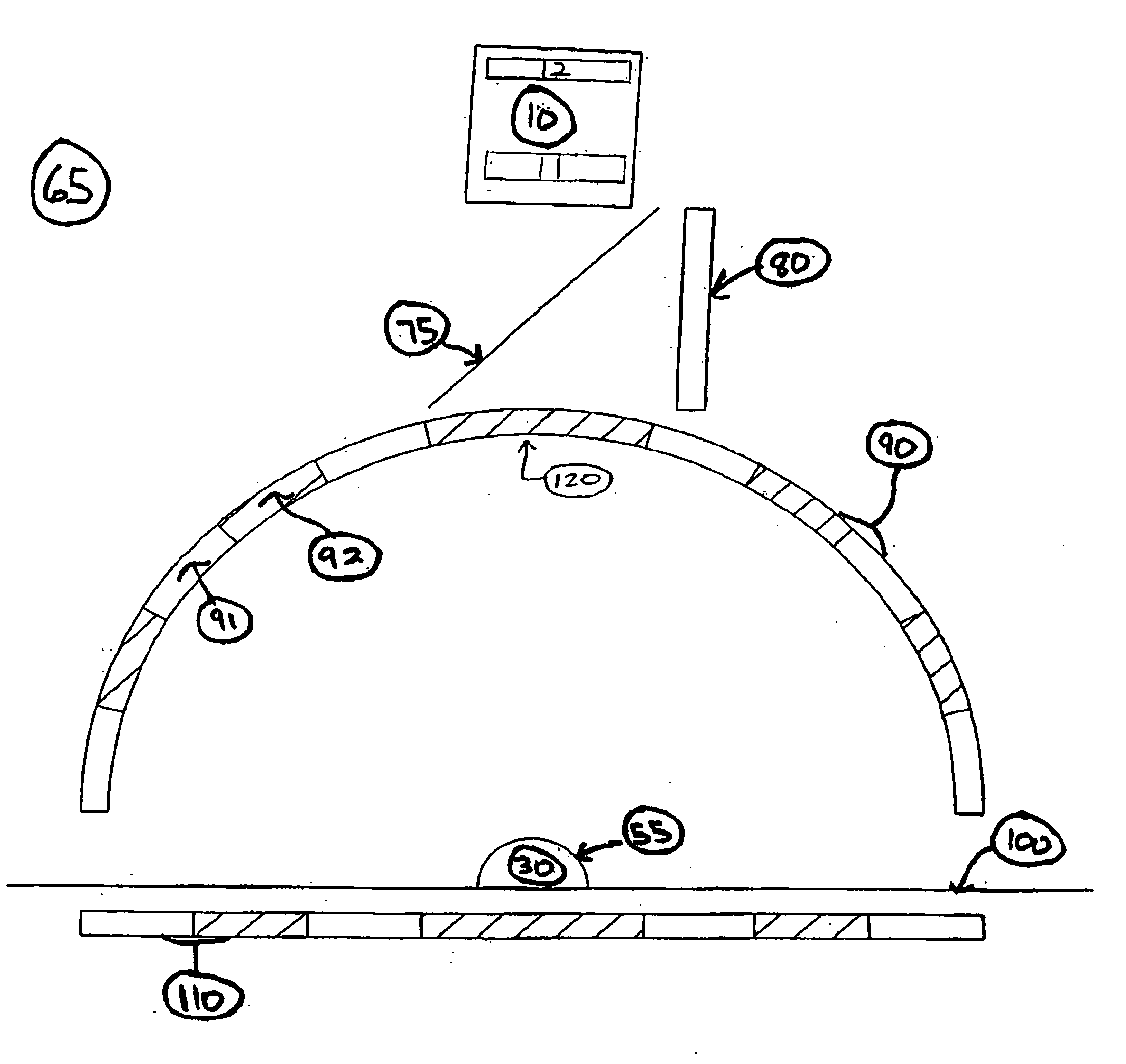
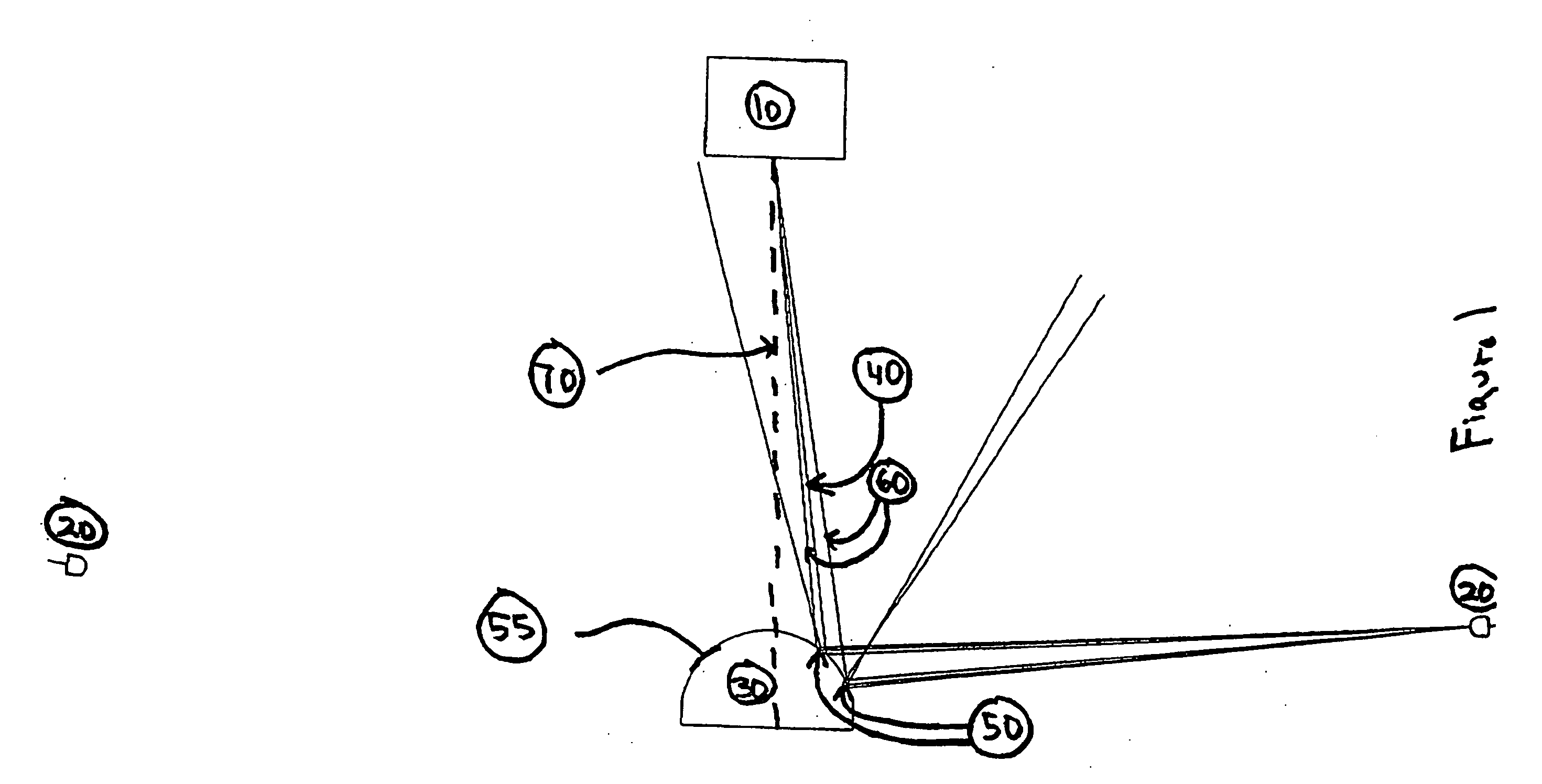
[0034] Referring now to the drawings wherein the showings are for the purposes of illustrating preferred embodiments of the invention only and not for purposes of limiting the same, FIG. 1 provides a cross-sectional schematic view of a prior art ringlight illuminator. As shown, the part under inspection 30 is illustrated as a domed object approaching the general shape of a hemisphere. Note that this choice of part shape is done for the purposes of illustration and should not be interpreted so as to limit in any manner the applicability of this invention to other areas of inspection.

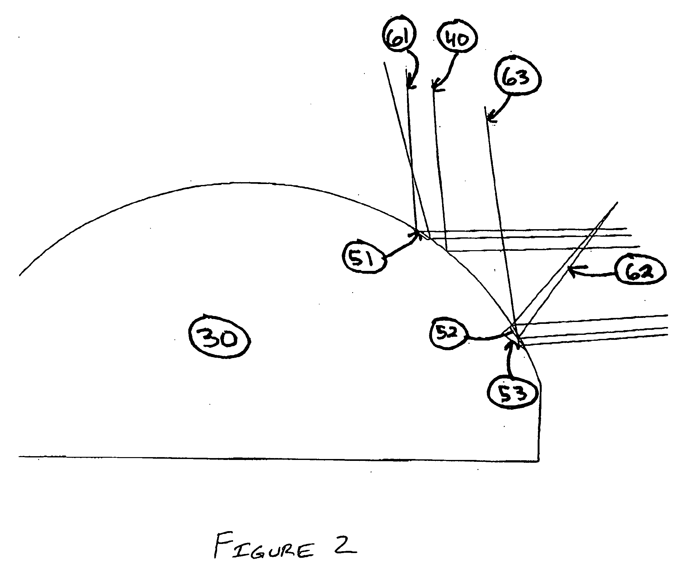
[0035] In this prior art implementation, light-emitting diodes (LEDs) 20 are deployed in an annular fashion and are used to generate a line source of generally narrow spatial extent that diverges from its emission point and is directed onto the surface 55 of a centrally located part under inspection 30. In this Figure, a single optical ray 40, emitted by the LED source 20, is ejected at an angle wherein ...


PUM


Abstract

This application relates to an apparatus and method for providing patterned illumination fields for use within process control and article inspection applications. More specifically, it pertains to the use of patterned illuminators to enable visual surface inspection of polished objects such as ball bearings. The use of patterned illuminators properly disposed in relation to a polished part under inspection allows small surface imperfections such as scratches and pits to become visible against the normal surface background. The use of carefully engineered illuminators facilitates advantageous defect-site scattering from generally dark field sources. The patterned nature of the illuminators defined by this invention allows the complete surface of three-dimensional parts to be effectively highlighted using dark field illumination fields.

Description

BACKGROUND OF THE INVENTION [0001] This application claims priority to the prior provisional patent application entitled “Patterned Illumination Method and Apparatus for Machine Vision Systems” bearing U.S. Ser. No. 60 / 390,839, filed Jun. 21, 2002. [0002] This application relates to an apparatus and method for providing patterned illumination fields for use within process control and article inspection applications. More specifically, it pertains to the use of patterned illuminators to enable visual surface inspection of polished objects such as ball bearings. While the invention is particularly directed to the art of high-speed automated process control and article inspection applications, and will be thus described with particular reference thereto, it will be appreciated that the invention may have usefulness in other fields and applications. For example, the invention may be used as an illumination source for manual or operator-initiated inspection of parts. [0003] By way of bac...

Claims


Application Information

Patent Timeline
IPC IPC(8): G01N21/86G01V8/00G01N21/84F21VG01N21/00G01N21/88G06M7/00G08B13/18H01J40/14
CPCG01N21/8806
Inventor COCHRAN, DON W.CECH, STEVEN D.PALOMBO, THOMAS H.YODER, MICHAEL L.BOOHER, JESSE C.GRAVES, TERRY L.
Owner PRESSCO TECH INC
Why Eureka
Try Eureka