Field emission luminescent light source

a field emission and luminescent light source technology, applied in the direction of discharge tube luminescnet screen, electrode system manufacturing, electric discharge tube/lamp manufacturing, etc., can solve the problems of incandescent lamp, low energy efficiency, and most of electric energy used to convert heat and was

Active Publication Date: 2006-05-04
HON HAI PRECISION IND CO LTD +1
View PDF9 Cites 24 Cited by
  • Summary
  • Abstract
  • Description
  • Claims
  • Application Information

AI Technical Summary

Benefits of technology

[0011] Even more preferably, the cathode filament

Problems solved by technology

However, because an incandescent lamp emits light by incandescence of a tungsten filament, most of electric energy used is converted into heat and wasted.
Therefore, a main drawback of the i

Method used


Image

  • Field emission luminescent light source
  • Field emission luminescent light source
  • Field emission luminescent light source

Examples


Embodiment Construction

[0022] Reference will now be made to the drawings to describe preferred embodiments of the present invention in detail.

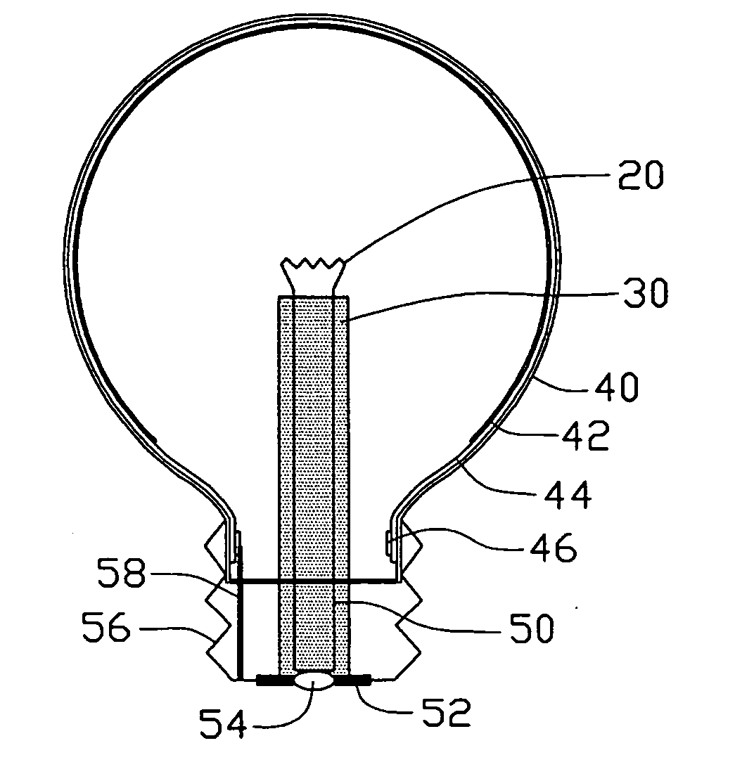
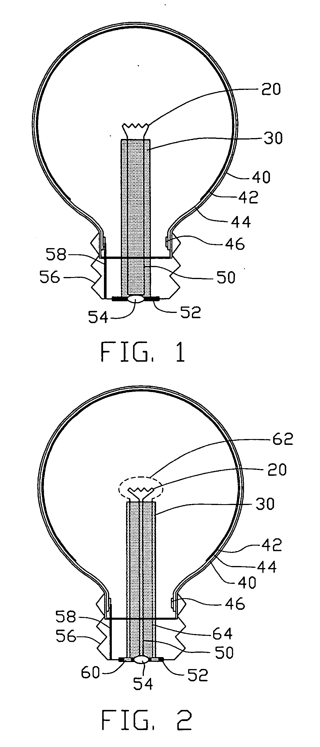
[0023] Referring to FIG. 1, a field emission lamp according to a first preferred embodiment of the present invention includes: a transparent glass bulb 40 used as a light-passable container of the lamp having a main portion (not labeled) and a neck portion (not labeled); a lamp head (not labeled) mated with the neck portion; an anode layer 44 formed on an inner surface (not labeled) of the bulb 40; a phosphor layer 42 formed on the anode layer 44; a cathode electrode 54 and an anode electrode 56 located at the lamp head; an anode down-lead ring 46 located at the neck portion of the bulb 40, the anode down-lead ring 46 engaging with the anode layer 44 and electrically connecting with the anode electrode 56 via an anode down-lead pole 58; and a cathode filament-like member 20 positioned in the bulb 40, wherein the cathode filament 20 is electrically connected with th...


PUM


Abstract

A field emission luminescent lamp includes a bulb (40) being vacuum sealed and defining an inner surface; a lamp head mated with the bulb; an electron emitting cathode filament (20) having a conductive wire (10) and a plurality of electron emitters (12) formed thereon, the electron emitting cathode filament is positioned in the bulb; an anode layer (44) formed on the inner surface of the bulb; a phosphor layer (42) formed on the anode layer; an anode electrode (56) located at the lamp head and electrically connected with the anode layer; and a cathode electrode (54) located at the lamp head and electrically connected with the electron emitting cathode filament. The lamp may further include a gate grid (62) and a gate electrode (54). The gate grid defines a number of grid holes and surrounds the cathode filament. The gate grid is electrically connected with the gate electrode.

Description

BACKGROUND OF THE INVENTION [0001] 1. Field of the Invention [0002] The present invention relates to a mercury-free light source, and more particularly to a cold cathode luminescent field emission device which is environmentally friendly and energy efficient. [0003] 2. Related Art [0004] Light sources for daily living are usually incandescent lamps or fluorescent tubes. Incandescent lamps have a long history since the first incandescent lamp invented by Thomas Edison in 1879. However, because an incandescent lamp emits light by incandescence of a tungsten filament, most of electric energy used is converted into heat and wasted. Therefore, a main drawback of the incandescent lamp is low energy efficiency. [0005] A conventional fluorescent tube generally includes a transparent glass tube, a phosphor layer coated on an inner surface of the glass tube, and a certain amount of mercury vapor filled in the glass tube. The mercury vapor in the glass tube is excited by an electrical discharg...

Claims


Application Information

Patent Timeline
IPC IPC(8): H01J63/04H01J1/62
CPCH01J63/06
Inventor LIU, PENGWEI, YANGSHENG, LEI-MEIQIAN, LITANG, JIELIU, LIANGGUO, CAI-LINDU, BING-CHUFAN, SHOU-SHAN
Owner HON HAI PRECISION IND CO LTD
Why Eureka
Try Eureka