
Optical image stabilizer for camera lens assembly

a technology camera lens assembly, which is applied in the field of optical image stabilization of camera lens assembly, can solve the problems of ccd sensor disadvantages of high power consumption and complicated structure, unstable images are frequently photographed, and the camera lens assembly is not easy to be downsized, so as to facilitate the downsizing of a product

Inactive Publication Date: 2006-05-04
SAMSUNG ELECTRONICS CO LTD
View PDF2 Cites 58 Cited by
  • Summary
  • Abstract
  • Description
  • Claims
  • Application Information

AI Technical Summary

Benefits of technology

[0014] Accordingly, the present invention has been made to solve the above-mentioned problems occurring in the prior art and provides additional advantages, by providing an optical image stabilizer for a camera lens assembly, which facilitates the downsizing of a product equipped with a camera lens assembly.
[0015] One aspect of the present invention is to provide an optical image stabilizer for a camera lens assembly, which ensures solidity and reliability of a product equipped with a camera lens assembly, while facilitating downsizing of the same product.

Problems solved by technology

However, CCD sensors have disadvantages of high power consumption and complicated structures.
When photographing moving images using image sensors, unstable images are frequently photographed due to the trembling of cameras resulting from external causes, such as the user's trembling hands and mounting of cameras on vehicles.
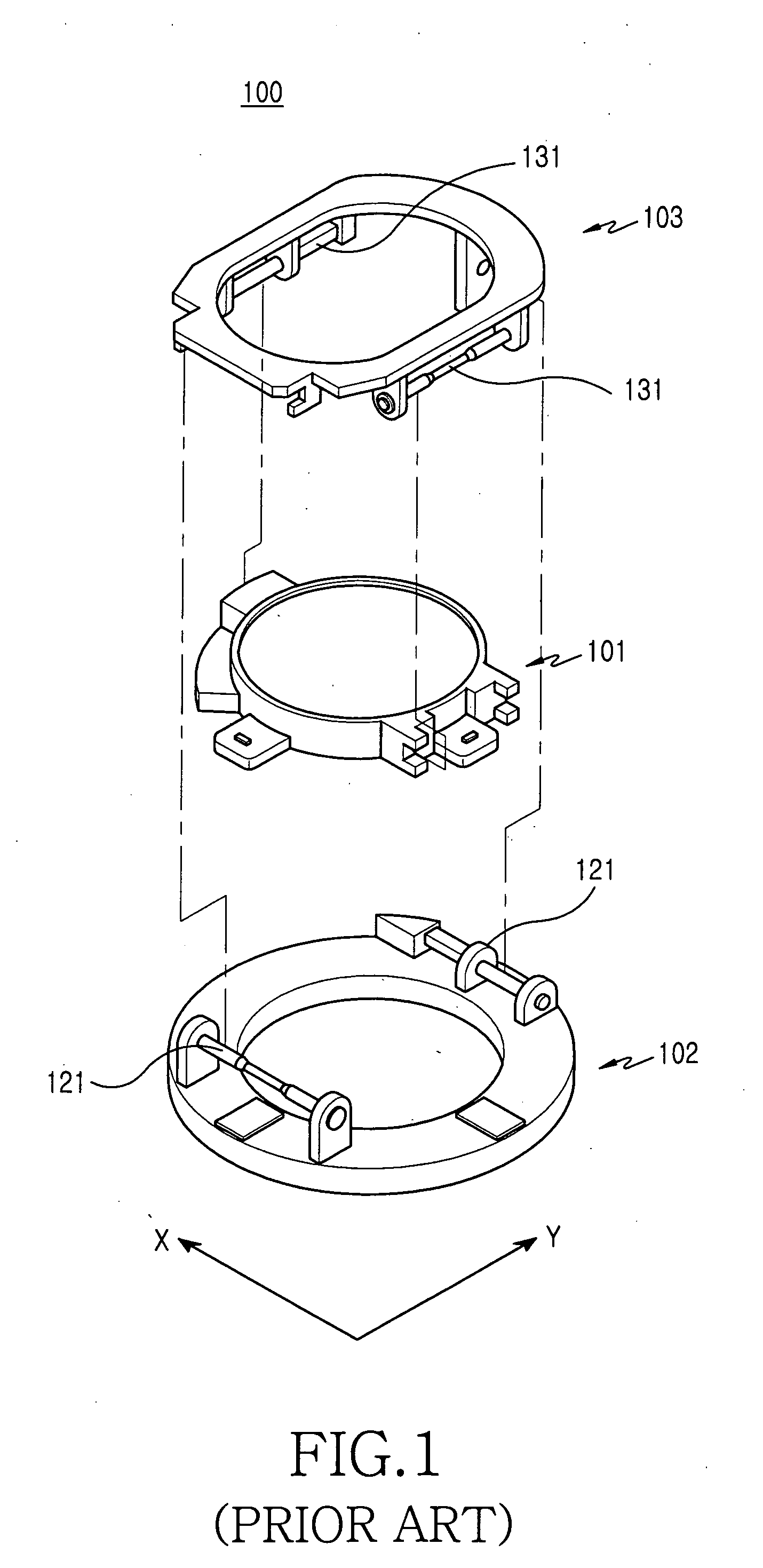
However, due to two stages on both surfaces of an image sensor, the conventional image stabilizer hinders the camera lens assembly from being downsized.
Therefore, it is difficult to mount a camera lens assembly on a product that requires a space for mounting an additional component, such as a portable terminal.

Method used


Image

  • Optical image stabilizer for camera lens assembly
  • Optical image stabilizer for camera lens assembly
  • Optical image stabilizer for camera lens assembly

Examples


Embodiment Construction

[0034] Hereinafter, embodiments of the present invention will be described with reference to the accompanying drawings. For the purposes of clarity and simplicity, a detailed description of known functions and configurations incorporated herein will be omitted as it may make the subject matter of the present invention unclear.

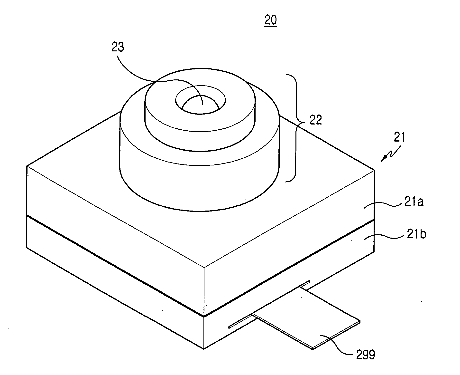
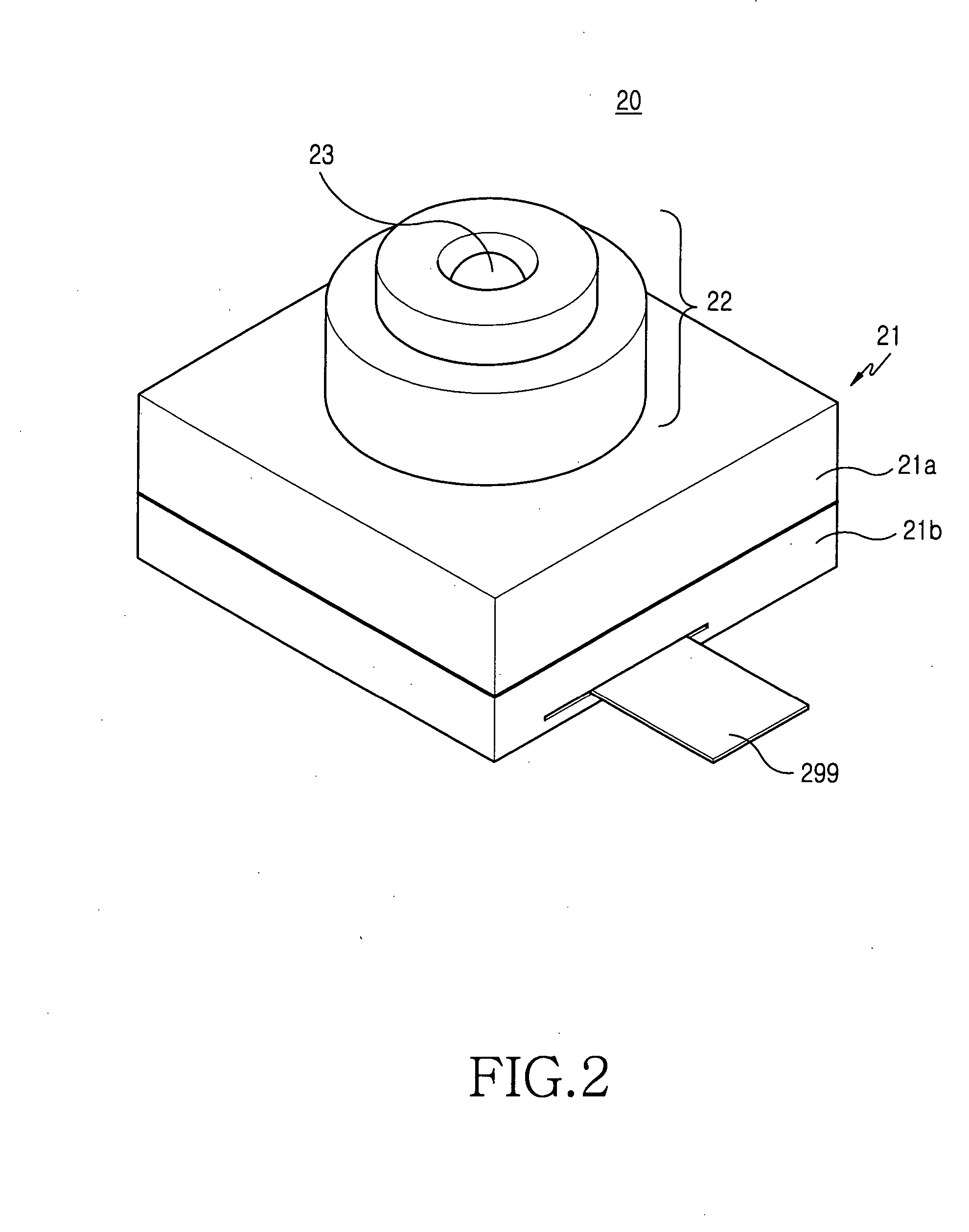
[0035] Referring to FIGS. 2 to 4, the optical image stabilizer 200 of the camera lens assembly 20 according to the present invention is disposed in a housing 21, more particularly in a lower housing 21b of the camera lens assembly 20. In operation, the optical image stabilizer 200 corrects the position of an image sensor 213 according to the trembling of user's hands to perform image stabilization.

[0036] The camera lens assembly 20 has a housing 21 including an upper housing 21a and a lower housing 21b, and an optical tube 22 in which at least one lens (not shown) is contained. The optical tube 22 extends from the upper housing 21a and has an exposure window ...


PUM


Abstract

An optical image stabilizer for a camera lens assembly includes: a board that has an image sensor on a top surface thereof and disposed movably in the housing, the board and the housing being spaced apart from each other; at least one magnetic body disposed between the board and the housing, the magnetic body providing a magnetic force acting in a direction along which the board is closely contacted to inner surface of the housing; at least three balls interposed between the board and the inner surface of the housing for maintaining the board in such a state that it is spaced apart from the housing; and a driving unit for correcting the position of the image sensor by moving the board according to the degrees of trembling of user's hands. In the optical image stabilizer for a camera lens assembly, the driving unit for driving the board, on which an image sensor is mounted, is present substantially on the same surface as the board itself. As a result, the optical image stabilizer can downsize a product equipped with a camera lens assembly and can improve the reliability of the product.

Description

CLAIM OF PRIORITY [0001] This application claims priority to an application entitled “Optical Image Stabilizer for Camera Lens Assembly,” filed in the Korean Intellectual Property Office on Nov. 3, 2004 and assigned Serial No. 2004-89033, the contents of which are hereby incorporated by reference. BACKGROUND OF THE INVENTION [0002] 1. Field of the Invention [0003] The present invention relates to a camera device, and more particularly to an optical image stabilizer for a camera lens assembly. [0004] 2. Description of the Related Art [0005] As is generally known in the art, a CCD (Charge Coupled Device) sensor and a CMOS (Complementary Metal Oxide Semiconductor) sensor are used for photographing dynamic and static images. Particularly, CCD sensors provide excellent characteristics compared to CMOS sensors in terms of image quality. However, CCD sensors have disadvantages of high power consumption and complicated structures. As such, CMOS image sensors are more popular in the market, ...

Claims


Application Information

Patent Timeline
IPC IPC(8): H04N5/228
CPCH04N5/2253H04N5/23248H04N5/23287H04N23/54H04N23/68H04N23/687H04N23/60
Inventor SHIN, DOO-SIK
Owner SAMSUNG ELECTRONICS CO LTD
Learn More