Unlock instant, AI-driven research and patent intelligence for your innovation.

Color-crossing error detection system and method for decoded composite video signals

a video signal and color-crossing error technology, applied in the field of digital image and video processing, can solve the problems of color-crossing error often appearing, color-crossing error occurring in both pal and ntsc video signals, and achieve the effect of small weighting factor and large weighting factor

Active Publication Date: 2006-05-04
ZHANGJIAGANG KANGDE XIN OPTRONICS MATERIAL
View PDF5 Cites 1 Cited by
  • Summary
  • Abstract
  • Description
  • Claims
  • Application Information

AI Technical Summary

Benefits of technology

[0011] For color-crossing error suppression in a decoded video signals, representing a plurality of fields, the present invention provides a novel two-technique method and system. Thus, in most embodiments of the present invention, a first suppression technique is used at the pixel for a first subset of fields that exhibit color-crossing error at the pixel location. Then a second suppression technique is used at the pixel location for a second subset of fields, that exhibit color-crossing error at the p

Problems solved by technology

Due to advancing semiconductor processing technology, integrated circuits (ICs) have greatly increased in functionality and complexity.
Imperfect decoding of composite video signals in either PAL or NTSC format may lead to color-crossing.
Specifically, color-crossing error often appears in a video image where the local luminance spatial frequency is near the sub-carrier frequency of the chrominance information.
Color-crossing errors occur in both PAL and NTSC video signals.
Thus the luminance components near the chrominance sub-carrier frequency cause color-crossing errors, which cannot be cleanly removed.
Color-crossing error can also occur in other encoded video signals.
While 3D comb filters can reduce color-crossing errors, 3D comb filters may also degrade other aspects of video quality.
For example, 3D comb filters are very sensitive to noise in composite video signals; therefore, a digital video decoder with a 3D comb filter would have difficulties with weak video signals, which are common in many areas.
Furthermore, high quality 3D comb filters are very expensive relative to other components of a video system.

Method used


Image

  • Color-crossing error detection system and method for decoded composite video signals
  • Color-crossing error detection system and method for decoded composite video signals
  • Color-crossing error detection system and method for decoded composite video signals

Examples


Embodiment Construction

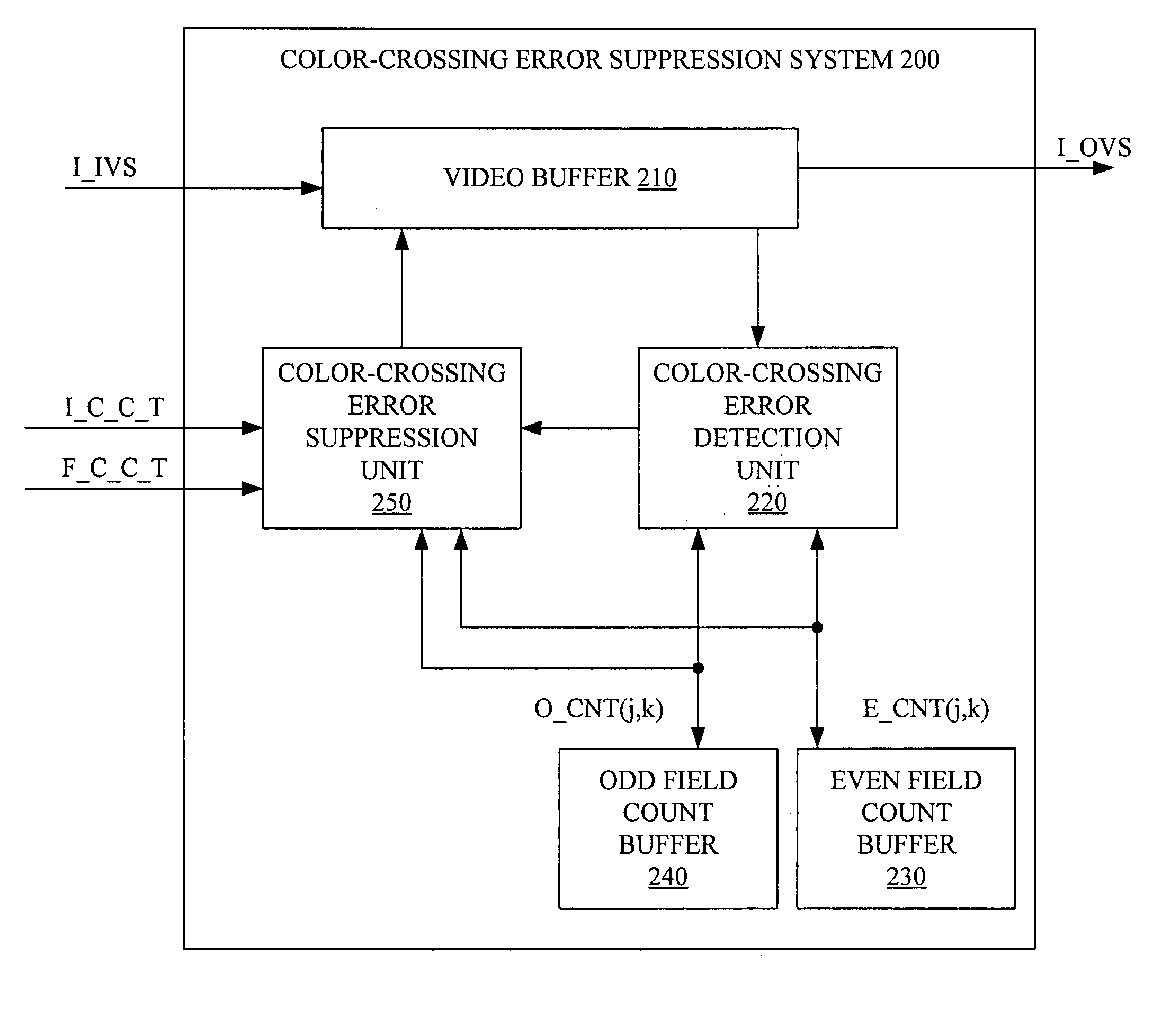
[0023] As explained above, imperfect decoding of composite video signals may cause color-crossing errors. The present invention detects and suppresses the color crossing errors in decoded composite video signals. FIG. 2 is a block diagram of a color-crossing error suppression system 200 in accordance with one embodiment of the present invention. Color-crossing error suppression system 200 includes a video buffer 210, a color-crossing error detection unit 220, an even field count buffer 230, an odd-field count buffer 240, and a color-crossing error suppression unit 250. Video buffer 210 includes multiple field buffers that store the most recent N fields from an incoming decoded interlaced video signal I_IVS. Color-crossing error detection unit 220 reads pixel information from the fields in video buffer 210 to detect color-crossing errors using odd field count buffer 240 and even field count buffer 230 as described below. Based on the detection from color-crossing error detection unit...


PUM


Abstract

A method and system for detecting color-crossing error in decoded video signals is presented. The color-crossing error detection method and system detects a color-crossing pattern in a set of corresponding pixels that share a pixel location. Each pixel of the set of corresponding pixels comes from a different field of a set of fields, which includes a current field having a current pixel. The method and system determines that color-crossing error exists at the current pixel when the color-crossing pattern exists for a user configurable number of sequential fields of the same field type at the pixel location.

Description

BACKGROUND OF THE INVENTION [0001] 1. Field of the Invention [0002] The present invention relates to digital image and video processing. More specifically, the present invention relates to methods of detecting and suppressing color-crossing errors for decoded video signals. [0003] 2. Discussion of Related Art [0004] Due to advancing semiconductor processing technology, integrated circuits (ICs) have greatly increased in functionality and complexity. With increasing processing and memory capabilities, many formerly analog tasks are being performed digitally. For example, images, audio and even full motion video can now be produced, distributed, and used in digital formats. [0005]FIG. 1 is an illustrative diagram of a portion of interlaced digital video signal 100 most often used in television systems. Interlaced digital video signal 100 comprises a series of individual fields F(0) to F(N). Even fields contain even numbered rows while odd fields contain odd numbered rows. For example ...

Claims


Application Information

Patent Timeline
IPC IPC(8): H04N5/213
CPCH04N5/213H04N9/646
Inventor ZHU, GE
Owner ZHANGJIAGANG KANGDE XIN OPTRONICS MATERIAL