Multiple parallel processor computer graphics system

a computer graphics and multi-parameter technology, applied in the direction of digital computers, processor architectures/configurations, instruments, etc., can solve the problems of reducing affecting the performance of the system, and preventing the cpu from performing other duties, so as to accelerate video graphics output and minimize delays

Inactive Publication Date: 2008-09-04
ALIENWARE LABS
View PDF68 Cites 73 Cited by
  • Summary
  • Abstract
  • Description
  • Claims
  • Application Information

AI Technical Summary

Benefits of technology

[0019]It will be observed by those skilled in the art and through experimentation that by utilizing multiple video cards, each processing only a portion of the screen, that the total throughput of the graphics subsystem is increased in proportion to the number of video cards. The throughput increase, however, is not infinitely extendible as the GCR module introduces at least minimal amounts of processing overhead which also increases in proportion to the number of video cards.
[0022]Therefore, embodiments of the present invention provide an accelerated graphics processing subsystem for use in computers that combines the processing power of multiple video cards, each one having one or more GPUs, and assigns each video card to process instructions for drawing a predetermined portion of the screen which is displayed to the user through a monitor or other visual output device. Embodiments of the present invention provide a graphics processing subsystem capable of accelerating video graphics output by combining multiple, off-the-shelf video cards without substantial modification. Other embodiments of present invention provide a graphics processing subsystem which does not require a high bandwidth connection between the video cards.
[0023]In another embodiment, the present invention organizes video processing by multiple video cards (or GPUs) such that each of the video cards is responsible for the video processing during different time periods. For example, two video cards may cooperate to provide video data to a display by taking turns, with the first video card controlling the display for a certain time period and the second video sequentially assuming video processing duties for a subsequent period. This configuration provides the advantage that while one video card is providing processed video data, the second video card is performing its processing of the next video data for the next time period, thereby minimizing delays since processing of the video data may be completed before the start of the next time period.

Problems solved by technology

Even before the beginning of the widespread use of personal computers, computer graphics has been one of the most promising, and most challenging, aspects of computing.
Because all of the processing was conducted by the CPU, graphics-intensive applications had a tendency to over-utilize processing cycles and prevent the CPU from performing other duties.
This led to overall sluggishness and degraded system performance.
The primary drawback with early GPU-based video cards was that there was no set standard for the “language” of the various high level commands that the GPUs could interpret and then process.
With hundreds of different GPU-based video cards on the market, application developers became bogged down in writing these specialized drivers.
This greatly slowed the development and adoption of new software.
One obvious and significant drawback with this system is that a high bandwidth pipeline must exist between the two GPUs.
No known devices, systems or methods provide a graphics processing subsystem for use in a computer that combines the processing power of multiple, off-the-shelf video cards, each one having one or more GPUs, and assigns each video card to process instructions for drawing a predetermined portion of the screen which is displayed to the user through a monitor or other visual output device.
In addition, none of the above devices describes a graphics processing subsystem capable of combining multiple, off-the-shelf video cards without substantial modification to the video cards.

Method used


Image

  • Multiple parallel processor computer graphics system
  • Multiple parallel processor computer graphics system
  • Multiple parallel processor computer graphics system

Examples


Embodiment Construction

[0029]While the present invention will be described more fully hereinafter with reference to the accompanying drawings, in which a preferred embodiment of the present invention is shown, it is to be understood at the outset of the description which follows that persons of skill in the appropriate arts may modify the invention herein described while still achieving the favorable results of this invention. Accordingly, the description which follows is to be understood as being a broad, teaching disclosure directed to persons of skill in the appropriate arts, and not as limiting upon the present invention.

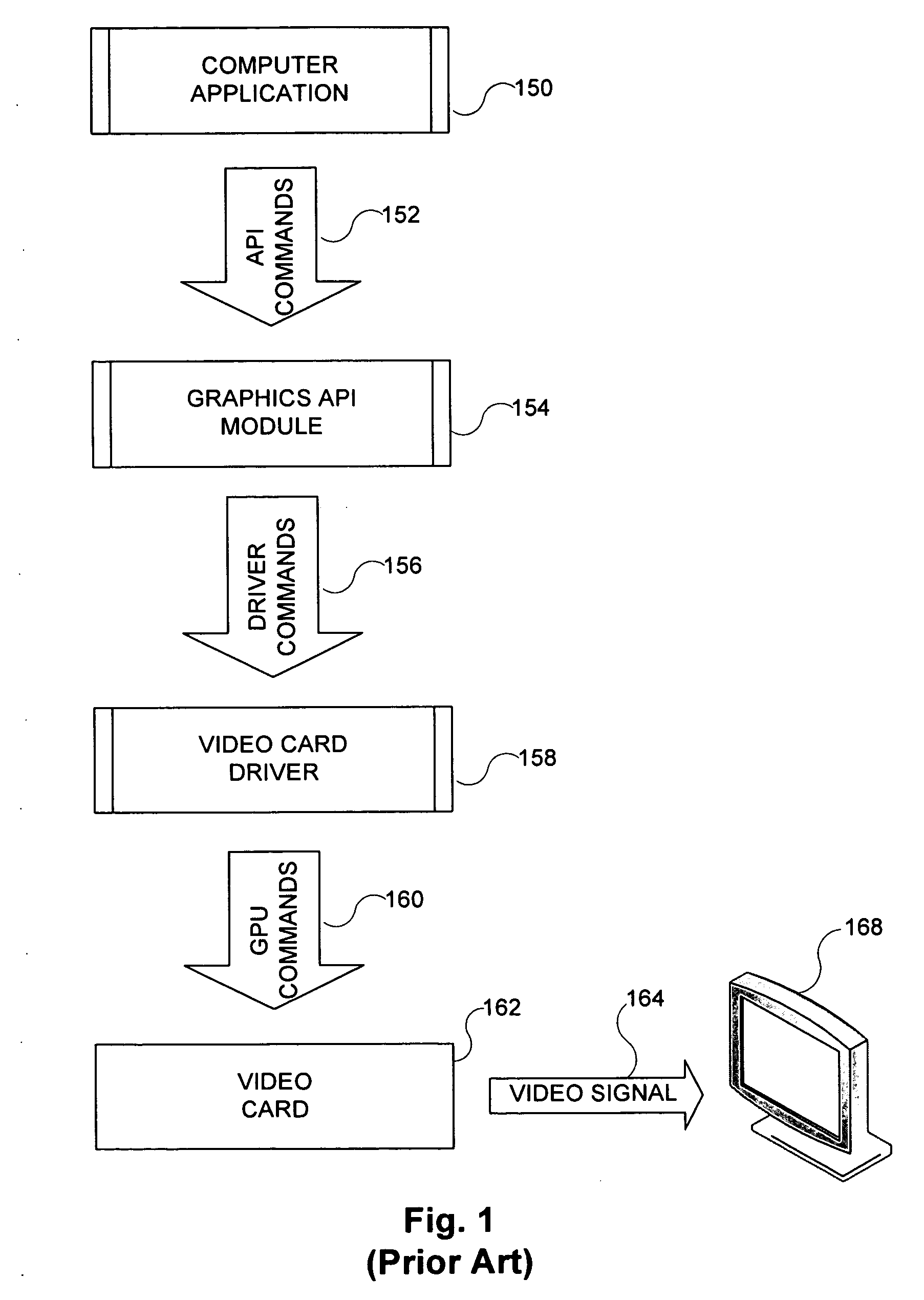
[0030]FIG. 1 is a block diagram illustrating a modern-day graphics subsystem within a computer typically configured without the present invention, and its interaction with typical personal computer software to generate an image.

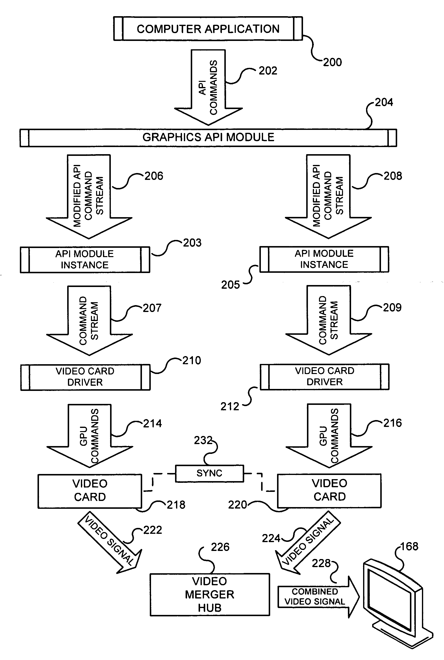
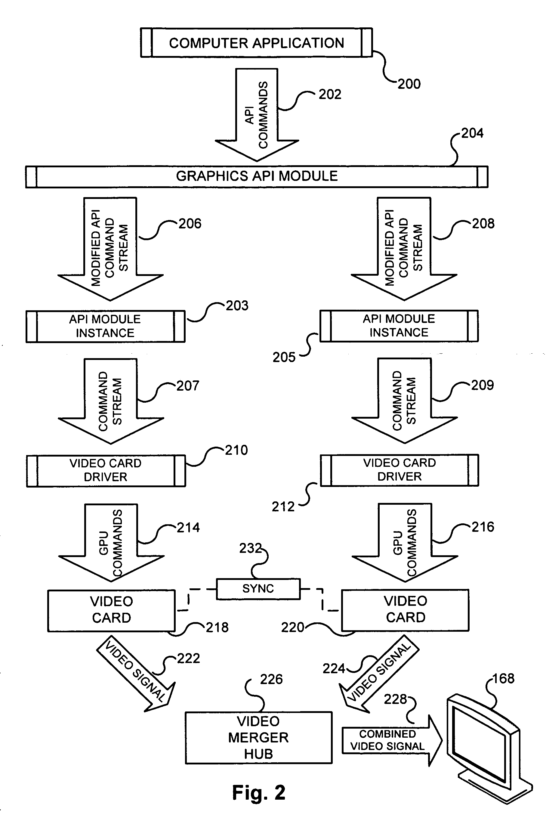
[0031]Under typical circumstances, a computer application 150, such as a game, 3D graphics application or other program, will generate API commands 152 for the...


PUM


Abstract

An accelerated graphics processing subsystem combines the processing power of multiple graphics processing units (GPUs) or video cards. Video processing by the multiple video cards is organized by time division such that each video card is responsible for video data processing during a different time period. For example, two video cards may take turns, with the first video card controlling a display for a certain time period and the second video sequentially assuming video processing duties for a subsequent period. In this way, as one video card is managing the display in one time period, the second video card is processing video data for the for the next time period, thereby allowing extensive processing of the video data before the start of the next time period. The present invention may further incorporate load balancing such that the duration of the processing time periods for each of the video cards is dynamically modified to maximize composite video processing.

Description

CROSS REFERENCE TO RELATED APPLICATIONS[0001]The present application is a continuation-in-part of U.S. non-provisional application Ser. No. 10 / 620,150, filed Jul. 15, 2003, the subject matter of which is hereby incorporated by reference in full.STATEMENT REGARDING SPONSORED RESEARCH OR DEVELOPMENT[0002]Not Applicable.REFERENCE TO SEQUENCE LISTING[0003]Not Applicable.BACKGROUND OF THE INVENTION[0004]1. Field of the Invention[0005]The present invention relates to the processing of graphics instructions in computers. Specifically, the preferred embodiment of the present invention discloses an accelerated graphics processing subsystem for use in computers that utilizes multiple, off-the-shelf, video cards, each one having its one or more graphic processor units (GPUs), and assigns each video card to alternately generate instructions for drawing a display. The video cards to be used in the disclosed invention need not be modified in any substantial way[0006]2. Description of Related Art[...

Claims


Application Information

Patent Timeline
Patent Type & Authority Applications(United States)
IPC IPC(8): G06F15/80G06F15/16
CPCG06F3/14G06T1/20G09G5/12G09G5/363G09G2360/123G09G2310/0224G09G2340/12G09G2352/00G09G5/42G06F15/80
Inventor GONZALEZ, NELSONORGANVIDEZ, HUMBERTOORGANVIDEZ, JUAN H.
Owner ALIENWARE LABS
Why Eureka
Try Eureka