Light emitting device for gloves

Inactive Publication Date: 2006-05-04
DNP KOREA
View PDF11 Cites 17 Cited by
  • Summary
  • Abstract
  • Description
  • Claims
  • Application Information

AI Technical Summary

Benefits of technology

[0008] The present invention has been made to solve the above and other problems, and it is an object of the present invention

Problems solved by technology

However, although the functional gloves of the disclosure are designed to prevent slippage of the tool from the hand only with the shape of the net cloths of the bottom plate, it is difficult in pra

Method used


Image

  • Light emitting device for gloves
  • Light emitting device for gloves
  • Light emitting device for gloves

Examples


Example

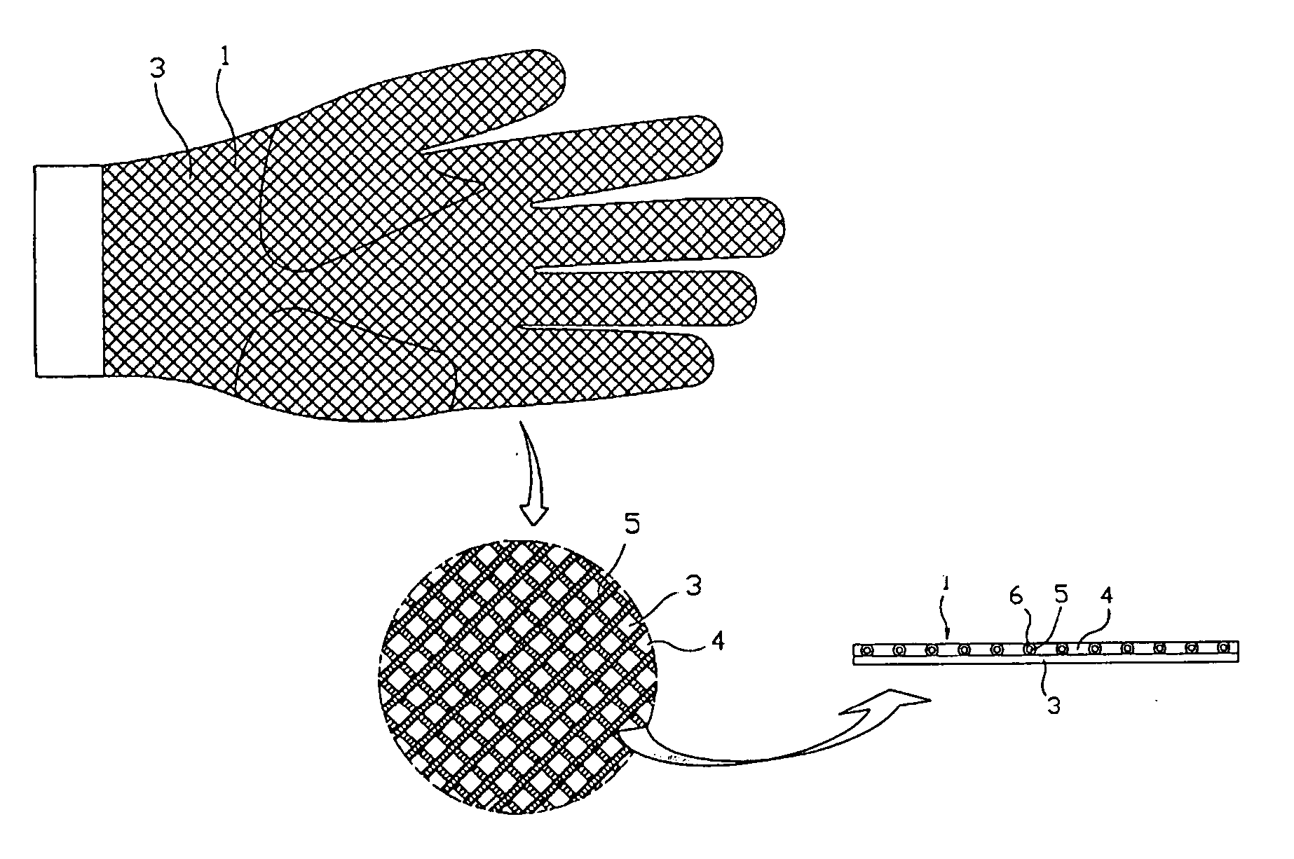
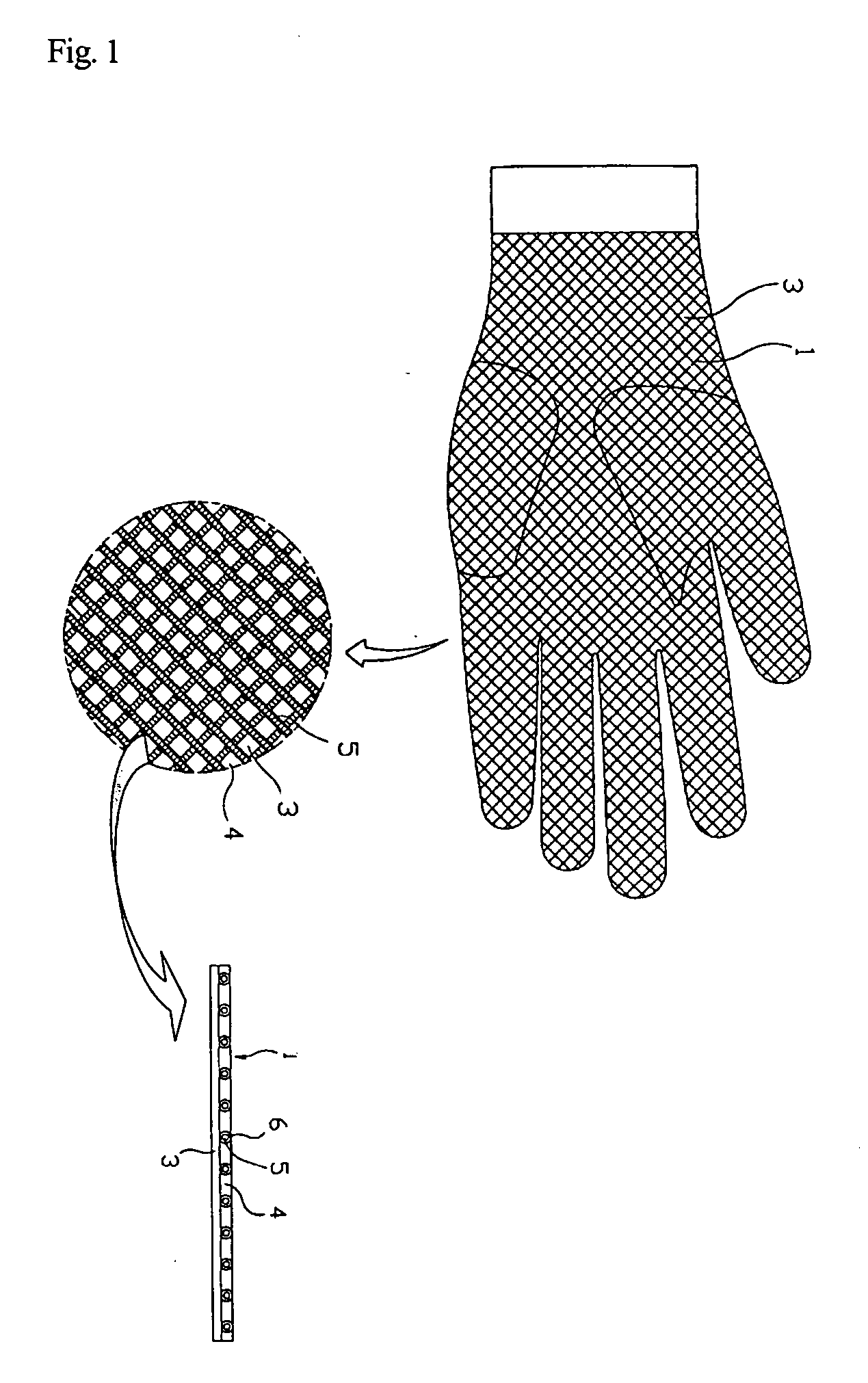
[0024] Preferred embodiments of the present invention will be described in detail with reference to the accompanying drawings.

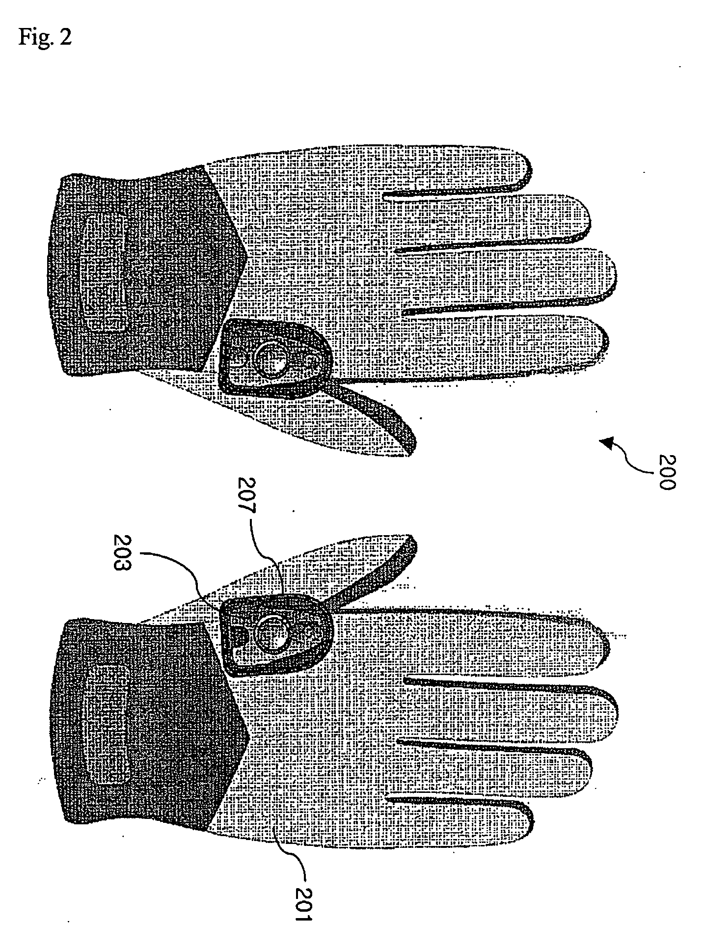
[0025]FIG. 2 is a view illustrating light emitting devices according to the present invention, in which the light emitting devices are attached to gloves 200. Each light emitting device comprises a holder 207 attached to an upper surface 201 of each glove 200, and a device controller 203 positioned on the holder 207 to control brightness of light via a switching operation. The holder 207 is a coupling member to attach or detach the device controller 203 to the glove, and is fixed at a predetermined position of each glove 200. The holder 207 is made of flexible fibers or a plastic material, if necessary, and is bonded or sewed to the predetermined position of the glove 200. More specifically, the holders 207 are attached to the upper surfaces 201 of the gloves 200 to allow the device controller 203 to be attached to or detached from the gloves via the holders...


PUM


Abstract

Disclosed herein is a light emitting device for gloves, which can be detached from the gloves when washing the gloves. The light emitting device comprises a holder fixed to one side of an upper surface of each glove, a lighting member, a device controller electrically connected with the lighting member to turn on or off the lighting member based on the selected on/off control modules after selecting a preprogrammed on/off control module in response to predetermined switching operations, and a fastening member to attach or detach the device controller to or from the holder. The gloves comprising the light emitting device can be widely used for various operational circumstances and recreations such as fishing, golf, and the like.

Description

BACKGROUND OF THE INVENTION [0001] 1. Field of the Invention [0002] The present invention relates to functional gloves, and, more particularly, to a light emitting device for gloves, which comprises a device controller detachably mounted at a predetermined position of each glove, and allows programmable control of turn on / off of the device controller to enhance functionality in operation with the gloves. [0003] 2. Description of the Related Art [0004] Generally, functional gloves can be classified into gloves to maintain a person's temperature, and gloves to protect person's hands during recreational activities or in industrial settings. The gloves are made of various materials including fabrics, leather, etc., and have various designs according to application. [0005] Various functional gloves are disclosed in Korean Utility Model Publications, which can enhance utility, stability and wearing sensation. For example, Korean Utility Model Registration No. 20-0348532 discloses gloves e...

Claims


Application Information

Patent Timeline
IPC IPC(8): F21V21/08A41D19/015A41D19/00
CPCA41D19/0157A41D1/002A41D13/01A41D19/01547A41D2600/20A41D2600/106
Inventor PARK, HYUNG-GYUN
Owner DNP KOREA
Why Eureka
Try Eureka